 MAKENEXA
Frames and structural bases
Define mounting planes, rail or bearing interfaces, diagonal relationships, load path and lifting or handling context. Identify which faces require post-weld machining or controlled support during inspection.
Manufacturing service decision
A weldment is accepted as a finished assembly, not as a collection of individually correct pieces. Joint design, access, heat input, sequence, restraint, distortion, post-weld machining, finish and inspection must support the same datum strategy. MakeNexa reviews the complete fabrication package across its network; supplier qualifications, procedures, tolerances, documents, price and timing remain RFQ-specific.
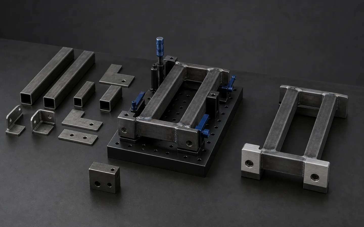
Route decision
Identify the surfaces, holes, axes and envelopes that locate the weldment in its parent assembly. Define whether those interfaces are welded as-is, machined after welding or inspected in a restrained condition. Submit component drawings, assembly model, weld symbols or joint requirements, BOM, material condition and relevant mating geometry. Do not rely on a general note to communicate every joint and acceptance expectation.
Heat and restraint can move long members, thin panels, closed frames and asymmetric joints. A reviewed route may use tack sequence, fixtures, balanced welding, controlled straightening, stress relief where appropriate or machining after welding. These choices depend on geometry, material, quantity, finish, inspection and governing requirements; they are not universal performance promises.
Best-fit parts and programs
The route is strongest when joint purpose, final interfaces and service context are visible before fabrication begins.
Define mounting planes, rail or bearing interfaces, diagonal relationships, load path and lifting or handling context. Identify which faces require post-weld machining or controlled support during inspection.
Joined plates and formed components can create geometry that is inefficient as one machined piece. Control part location, joint access, seam visibility, distortion and accumulated tolerance across components.
Use machining after welding when bores, pads or mounting faces must share final relationships. Provide machining stock, datum transfer, clamping access and the state in which the weldment is stable enough to finish.
Leak, cleanliness or contamination requirements need defined joints, access, cleaning, test method, acceptance and evidence. A continuous-looking seam alone does not establish service performance.
Feasibility checks
Generic weld callouts can hide the exact conditions that drive routing, rework and inspection.
The final assembly needs a datum scheme tied to installation and inspection. State how component datums transfer through fixtures, weld sequence and post-weld machining.
Joint size, length, continuity, side, contour, access and finish influence heat, strength, appearance and cost. Use the governing drawing convention and identify any project-specific procedure or evidence need.
Large or flexible fabrications may sit differently free, supported or bolted down. Define the accepted support or restraint and avoid tolerances that cannot be reproduced during inspection.
Grinding, blasting, coating, passivation or paint can alter appearance and interfaces. Define visible seams, cleanup limits, masked datums, drainage and inspection before finish.
Route options
Compare the complete assembly route, including distortion, access, finish, maintenance and inspection.
Use welds where permanent joined construction fits material, access and service. Scope joint requirements, fixtures, sequence, cleanup and final acceptance together.
Bolts, rivets, inserts or interlocking forms may reduce heat input, support disassembly or simplify mixed-material construction. Review joint access, loosening, hardware control and final envelope.
A machined base with welded or bolted members may protect critical interfaces while controlling cost and mass. Treat post-weld machining and hardware as part of one datum plan.
Decision comparison
Typical published practice for fabricated weldments. Achievable flatness, position and distortion depend on material, joint design, sequence and the supplier's process control, and the project requirement is confirmed on the reviewed quote rather than from this table.
| Decision layer | Typical published value | Routing consequence |
|---|---|---|
| As-welded distortion | A welded assembly commonly moves 1 mm per metre and more, far beyond any machining tolerance | Critical interfaces are machined after welding, not before |
| Machining sequence | Weld, stress relieve where required, then machine the interfaces that must hold position | Which dimensions apply before welding and which after |
| Stress relief | Commonly around 590 to 650 °C for carbon and low-alloy steel assemblies | A specified operation with its own acceptance criteria |
| Flatness as welded | Commonly 1 mm per metre; a flatness requirement tighter than that implies a machining or flattening operation | Whether the requirement carries a process with it |
| Fillet weld size | Commonly 3 mm to 6 mm on light fabrication; an oversized fillet adds heat, distortion and cost without adding strength | Weld size stated rather than left to the welder |
| Free-state measurement | A weldment measured while clamped is not the weldment in the free state | The support method and measurement condition stated on the drawing |
| Datum strategy | Datums should be established on machined surfaces created after welding, not on as-welded faces | The most common cause of an unbuildable weldment drawing |
| Material thickness mismatch | Welding thin to thick concentrates heat in the thin member and distorts it preferentially | Joint design reviewed against member thicknesses |
| Stainless distortion | 304 expands about 17.3 µm per metre per °C, roughly 45% more than carbon steel, and conducts heat away more slowly | Stainless weldments distort more for the same joint |
| Aluminium heat-affected zone | 6061-T6 loses its T6 strength in the heat-affected zone unless re-treated, dropping toward the annealed condition | Joints designed away from the highest-stress section |
| Weld inspection | Visual, dye penetrant, magnetic particle, ultrasonic and radiographic each answer different questions at different cost | Which method, which joints, and what acceptance criteria |
| Welder and procedure qualification | Qualification is specific to process, material, thickness and position — it is not a general certification | Which qualification is required, stated in the RFQ |
| Machining tolerance for comparison | A machined interface holds ±0.125 mm as standard practice and ±0.025 mm as precision work — three orders below as-welded movement | Why the machining follows the welding rather than preceding it |
| Stress-relief range | Commonly 590 °C to 650 °C for carbon and low-alloy steel; the lower end where distortion risk outweighs full relief | The specification and the temperature stated, not just the word relieved |
| Thin-member limit | Below about 1.5 mm, heat input distorts the member faster than the joint can be controlled | Whether the joint design suits the thinner member |
| Structural plate specification | ASTM A36 is the usual reference for structural plate and shapes in a fabricated weldment | Which specification the mill certificate must reference |
| Machined-after-weld allowance | 2 mm to 5 mm of stock left on interface faces so distortion can be cleaned up | Too little allowance and the machined face does not clean up |
| Fit-up gap | Root gaps are commonly held within 1.5 mm; wider gaps need more filler, more heat and more distortion | Whether cut-part tolerances support the joint design |
Quote inputs
Submit the complete assembly and final-interface requirement, not only component cut files.
Complete packages move faster: revision-matched CAD, critical dimensions, quantity and material notes are enough to open engineering review across the network.
Get a QuoteProvide controlled assembly and component models, drawings, BOM and revisions
State materials, conditions, joint requirements and governing drawing conventions
Identify load path, final datums, mounting faces, critical axes and envelope
Define accepted restraint state, distortion limits and post-weld machining stock
List cleanup, finish, masking, sealing, cleanliness and packaging requirements
Provide quantities, supplier or procedure qualifications, inspection, tests and documents
Questions before routing
These answers prepare the request; the reviewed quote controls project-specific commitments.
After, essentially always. A welded assembly commonly moves 1 mm per metre and more, which is orders of magnitude beyond a machining tolerance — so a hole positioned perfectly before welding is not positioned afterward. The normal sequence is weld, stress relieve where required, then machine the interfaces that must hold position. State clearly which dimensions apply before welding and which after.
With a number, a measurement method and a free-state condition. As-welded flatness is commonly around 1 mm per metre, so a requirement tighter than that implies a machining or flattening operation and should be priced as one. A weldment measured while clamped is also not the weldment in the free state — state the support method and the measurement points, or the requirement will not repeat between supplier and receiving inspection.
On machined surfaces created after welding, not on as-welded faces. This is the most common cause of a weldment drawing that cannot be built to: an as-welded surface carries the distortion, so any dimension measured from it inherits it. Establish the datum scheme on the faces that will be machined last, and make sure those faces are the ones that locate the assembly in service.
No. An image shows appearance at one moment from one angle; weld quality is a question of penetration, fusion, porosity, undercut and cracking, most of which are not visible on the surface at all. The evidence comes from a stated inspection method — visual, dye penetrant, magnetic particle, ultrasonic or radiographic — applied to named joints with stated acceptance criteria. State which joints are critical and what evidence is required.
Welding qualification is always specific to process, base material, thickness range and position — there is no single credential that covers everything, which is why the requirement should be stated rather than assumed. The supplier network includes fabricators holding ISO 9001 certification with qualified welding procedures and welder qualifications across the common processes and materials, and NADCAP-accredited welding where a programme requires it. Procedure records, welder qualification records and inspection reports — visual, dye penetrant, magnetic particle, ultrasonic or radiographic — are all requestable. State the process, material, thickness and required qualification and supplier fit is confirmed on the reviewed quote.
Next step
Send geometry and process requirements for review. MakeNexa routes capable suppliers from a global network covering competitor-class process categories, then returns a prepared quote or focused clarification for your revision.