 MAKENEXA
Walls and transitions
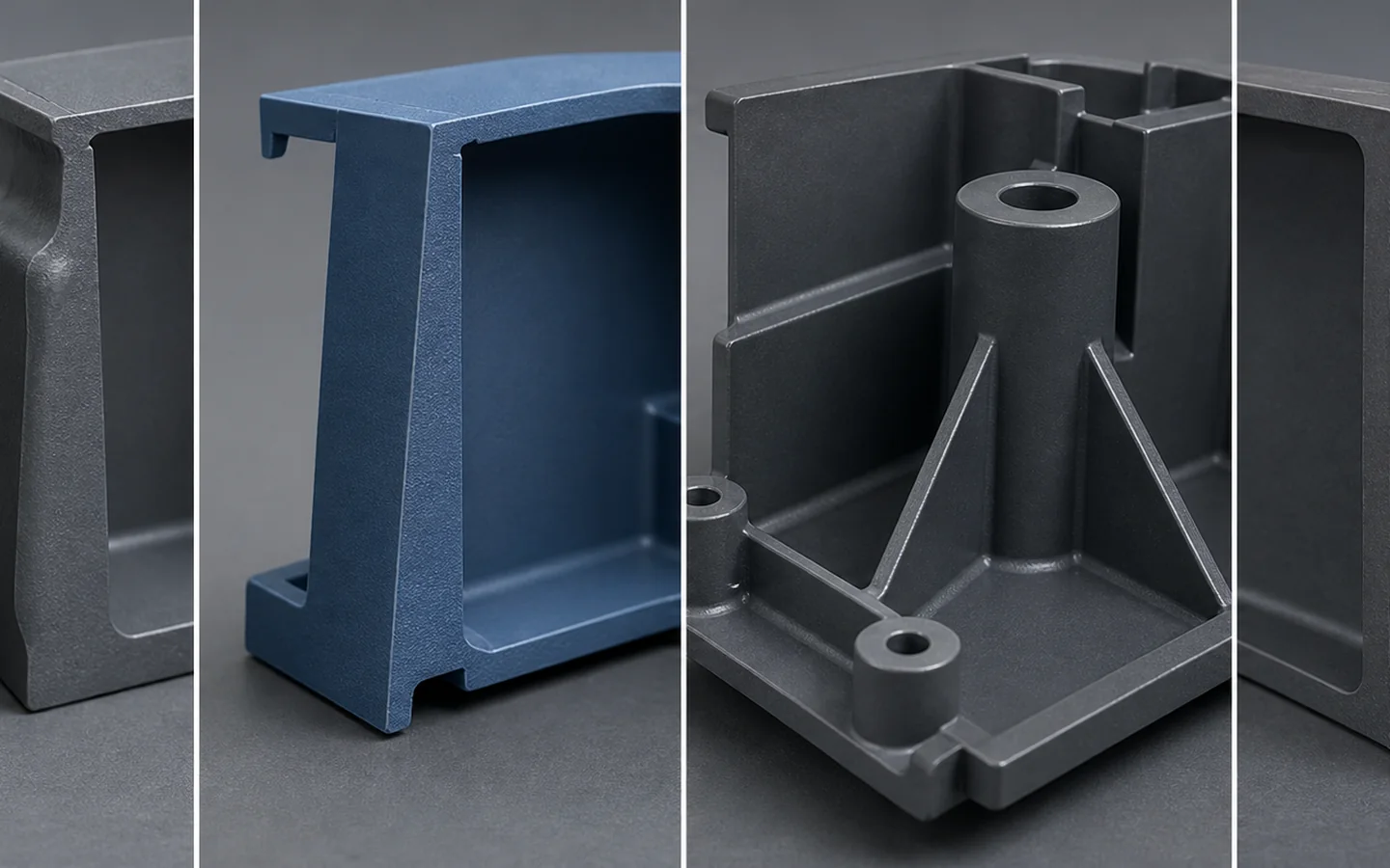
Consistent sections and deliberate transitions can reduce sink, void, cooling and warp risk when function permits.
Engineering design resource
Prepare a molded component and program for a focused tooling review. This guide organizes resin, wall strategy, draft, ribs, bosses, undercuts, gates, ejection, texture, tolerance, inspection and demand before MakeNexa routes the RFQ.
Use this guide
Injection molding design is not only about adding draft. The part must fill, pack, cool, shrink and eject while protecting functional and cosmetic surfaces. Wall transitions, ribs, bosses, deep cores, undercuts and gate location influence sink, warp, knit lines, pressure and tool construction. The practical answer depends on resin, part scale, finish, tolerance, quantity and the selected supplier route.
Tool strategy also depends on program maturity. Prototype, bridge and production tools can differ in material, cavities, actions, monitoring, maintenance and transfer expectations. Buyers should state first order, repeat pattern and credible lifetime range with change risk. MakeNexa reviews the system and confirms tool scope, samples, part price, lead time and project-specific capability in the quote.
Design priorities
Each feature affects plastic flow, cooling, tool access, ejection or final appearance.
Consistent sections and deliberate transitions can reduce sink, void, cooling and warp risk when function permits.
Pull direction, depth, texture and resin influence the draft needed for release without damage.
Structural features should support loads and fasteners while managing local thickness, sink and tool access.
Slides, lifters, collapsible features, inserts or redesign may resolve geometry that cannot eject in the main direction.
Common review gaps
Buyer input is needed where process marks, interfaces or commercial scope affect the product.
Mark appearance, sealing, load and flow-sensitive regions so the supplier can propose feasible locations.
Visible and functional faces need limits for pins, seams, flash and witness marks.
Control interfaces and datums in the final conditioned part rather than tightening every molded dimension.
Ownership, storage, maintenance, samples, changes, life assumptions and transfer should be written into scope.
Practical choices
The route should reflect quantity, complexity, change risk and required part evidence.
Core-outs, accessible pull directions and separate components may reduce actions when assembly remains acceptable.
Integrated hardware or materials can add function but require loading, interface and testing controls.
Bridge or project-specific tools may answer demand and design questions before a larger production commitment.
Design decision table
Typical published design practice for injection-moulded thermoplastics. Achievable geometry depends on resin, tooling and process, and the project requirement is confirmed on the reviewed quote rather than from this table.
| Design area | Typical published value | Supplier review |
|---|---|---|
| Nominal wall | 1.0 mm to 3.0 mm for most thermoplastics, held uniform within about 25% of nominal | The single most important rule — most defects trace back to it |
| Draft angle | 1° to 2° minimum on unfilled resins; 3° to 5° on textured surfaces | Zero-draft walls drag, scuff and can lock in the tool |
| Rib thickness | 50 to 60% of the adjoining wall, with height under about 3 times the wall | Thicker ribs sink visibly on the opposite face |
| Boss geometry | Outside diameter about twice the inside diameter, cored rather than solid, supported by a rib | A solid boss is a thick section and sinks |
| Corner radii | At least 0.5 times the wall thickness on internal corners | Sharp corners restrict flow and concentrate stress |
| Shrinkage | About 0.5% for ABS, 0.6% for polycarbonate, 1.5% for nylon, 2.5% for acetal | The tool is cut for one resin; changing resin means changing the tool |
| Achievable tolerance | Commonly ±0.1 mm on small features, widening with wall thickness and part size | Which dimensions are critical, stated with the resin |
| Cooling and cycle | Cooling dominates cycle time and scales with the square of the thickest section | Reducing a 3 mm wall to 2.0 mm cuts cycle substantially for the tool's life |
| Undercuts | Require side actions, lifters or a redesign, each adding tool cost and cycle time | Whether the undercut is functional |
| Knit lines | Form wherever flow fronts rejoin, typically behind holes and bosses, and are weaker | Where a knit line is permitted relative to load |
| Gate and ejector marks | Every part carries a gate vestige and ejector witness somewhere | Where they are permitted, marked on the drawing |
| Resin drying | Polycarbonate, nylon, PC-ABS and PEEK must be dried before moulding | A process control, not an optional step |
| Typical housing nominal | 2.0 mm is the usual starting wall for a moulded housing; a 3 mm wall roughly doubles cooling time | Wall thickness reviewed before the tool is cut |
| Radius on a thin wall | At least 0.5 mm on internal corners of a 1 mm wall, scaling with thickness | Sharp corners restrict flow and concentrate stress |
| Achievable tight tolerance | ±0.05 mm on small features in a stable resin with process control and added inspection | Which few dimensions justify it |
| Melt temperature by resin | Commonly 250 °C for ABS and up to 320 °C for polycarbonate | Whether inserts and hardware tolerate the process |
| Mould temperature | Commonly 40 °C to 80 °C circulating water, affecting surface finish and shrinkage directly | Why the same tool gives different parts on a different press |
| Tool surface effect | A polished cavity gives part surfaces near Ra 0.4 µm; a machined cavity leaves visible tool marks | The finish grade named rather than described |
Turn the guide into an RFQ
Keep the part definition and program assumptions in one package.
Complete packages move faster: revision-matched CAD, critical dimensions, quantity and material notes are enough to open engineering review across the network.
Get a Quote3D model and drawing with critical and cosmetic requirements
Exact resin, additives, color, records and permitted alternatives
Pull direction, draft, undercuts, texture, gate and witness restrictions
Interfaces, loads, conditioning, tests and final inspection state
First order, repeats, lifetime demand and design-change confidence
Tool ownership, samples, maintenance, storage, transfer and packaging
Questions before routing
These answers prepare the request; the reviewed quote controls project-specific commitments.
1° to 2° as a minimum on unfilled resins, rising to 3° to 5° on textured surfaces and scaling with texture depth. Zero-draft vertical walls drag on ejection, scuff visibly and can lock the part in the tool. Draft is cheapest to add at the design stage — retrofitting it after a tool is cut means removing tool material, which is straightforward only in the steel-safe direction.
No — every moulded part carries a gate vestige somewhere, and every part carries ejector pin witness too. What is possible is choosing where they land. Gate position also affects flow, knit-line placement behind holes and bosses, and warp, so it is an engineering decision rather than purely cosmetic. Mark on the drawing which surfaces are cosmetic and where gate and ejector marks are permitted.
Because thick sections cool and shrink last, pulling the surface in and leaving sink marks, and cooling differentially warps the part. Hold the nominal wall at 1.0 mm to 3.0 mm with variation under about 25%, ribs at 50 to 60% of the adjoining wall, cored rather than solid bosses, and radii of at least 0.5 times wall. Cycle time also scales with the square of the thickest section, so uniform thin walls save money on every shot for the tool's life.
When the resin is fixed, the wall is uniform, draft is applied everywhere, undercuts are resolved or accepted as actions, the critical dimensions are named with tolerances, and the cosmetic surfaces and permitted gate and ejector locations are marked. The resin matters most: shrinkage ranges from about 0.5% for ABS to 2.5% for acetal, and the tool is cut for one of them. Cut the first tool steel-safe wherever a dimension is uncertain.
Usually cooling layout or fibre orientation. Even a uniform wall warps if one side cools faster than the other, which is why cooling circuits are designed with the tool rather than added afterward. In glass-filled grades the fibres align with flow, making shrinkage directional — the part shrinks less along the flow than across it. Gate position, which controls flow direction, therefore affects warp as much as wall thickness does.
Next step
Apply the guide to a real drawing and RFQ package. MakeNexa routes capable suppliers from a global network covering competitor-class process categories, then returns a prepared quote or focused clarification for your revision.