 MAKENEXA
Threaded interfaces
Knurled nuts, studs and threaded bushings can provide repeat fastening when torque, pull-out and boss geometry are coordinated.
Manufacturing service decision
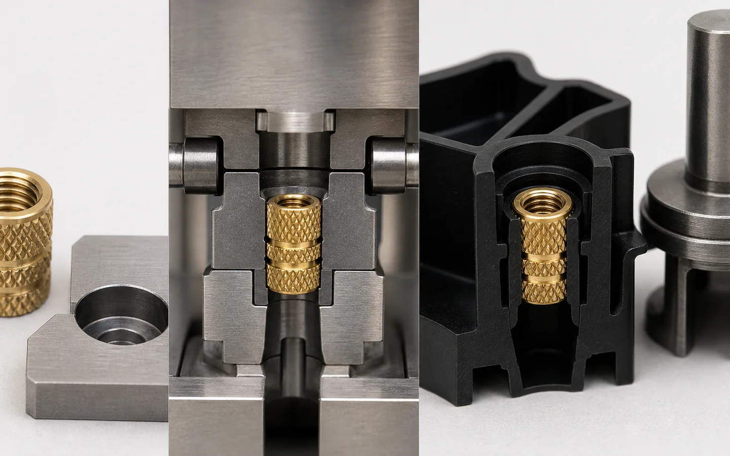
Source plastic parts molded around threaded inserts, contacts, bushings, shafts, magnets and other controlled components. MakeNexa reviews insert material and condition, location, retention, resin flow, loading method, tooling, quantity and functional tests before confirming the manufacturing route.
Route decision
Insert molding can reduce assembly steps and create robust mechanical or electrical interfaces, but the insert becomes part of the molding process. Its dimensional variation, plating, cleanliness, orientation, thermal mass and feeding condition can affect loading, tool closure, plastic flow, flash, knit lines and final location. A catalog number alone may not communicate the incoming condition needed by the tool.
MakeNexa reviews whether inserts are customer-supplied, supplier-sourced or made within the routed program; how they are verified and loaded; and how retention, torque, electrical continuity, sealing or positional accuracy will be tested. Manual and automated loading have different tooling and volume implications. Exact resin, insert source, tool, supplier, tolerance, price and timing are confirmed per RFQ.
Best-fit parts and programs
Each insert should have a defined role, retention mechanism and acceptance method.
Knurled nuts, studs and threaded bushings can provide repeat fastening when torque, pull-out and boss geometry are coordinated.
Contacts, terminals and lead frames require controlled location, plating protection, insulation boundaries and electrical tests.
Bushings, shafts and bearing surfaces may integrate durable interfaces when molding pressure and final concentricity are addressed.
Orientation-sensitive or fragile components need positive location, handling controls and a way to verify presence and polarity.
Feasibility checks
Small incoming variation can become a molded-part defect or tool-protection problem.
The insert needs repeatable datums, mistake-proof loading and support against movement under injection pressure.
Threads, bores, contacts and sealing surfaces may need shutoffs, plugs or post-mold cleaning with explicit limits.
Knurls, grooves, flats, holes and undercuts transfer load differently and can influence stress in the molded resin.
Burrs, oil, plating variation, mixed lots or damaged inserts can affect bond, fit, appearance and loading reliability.
Route options
Molded-in integration should be compared with installation after molding and separate assembly.
Useful when encapsulation, precise integration or assembly reduction justifies loading and dedicated tool features.
Compared for threaded hardware when post-mold access, volume, boss design and service loads support installation.
Separate fastening or retention may offer easier replacement, inspection and change control for some components.
Decision comparison
Define the incoming insert, molded interface and final test as one purchasing package. The dimensional and temperature figures below are typical published practice; the values for a specific insert, resin and tool are confirmed on the reviewed quote.
| Decision area | What to provide and typical values | Review focus |
|---|---|---|
| Insert | Drawing, material, finish, source, tolerances, supplied packaging and records. Insert diameter tolerance is normally held to ±0.05 mm where the tool locates on it. | Incoming consistency, loading and tool protection |
| Plastic | Exact resin, additives, color, shrink, environment and alternatives. Melt temperatures run near 220 to 250 °C for ABS, 280 to 300 °C for nylon 6/6 and 280 to 320 °C for polycarbonate. | Flow, stress, insulation and service behavior |
| Boss geometry | At least 1.5 mm of resin wall around the insert, and a nominal wall of 2 to 3 mm through the surrounding section so the boss does not sink or void | Knit-line position, shrink stress and cracking around the insert |
| Interface | Location, retention features, shutoffs, protected surfaces and molding boundaries. Insert position after molding is typically held to ±0.1 to ±0.25 mm depending on how the tool captures it. | Movement, flash, knit lines and final position |
| Thermal stress | Steel inserts are often preheated to 100 to 150 °C before loading; a cold insert in a 280 °C melt drives a shrink gradient that cracks the boss | Residual stress, micro-cracking and long-term retention |
| Production | Quantity, repeats, customer-supplied or sourced status and loading expectations | Manual or automated route and inventory control |
| Acceptance | Presence, position, pull, torque, leak, electrical and visual criteria, with tensile behaviour referenced to ASTM D638 where the resin datasheet is the basis | Test method, sampling and traceability |
Quote inputs
Include insert supply and handling data with the final-part definition.
Complete packages move faster: revision-matched CAD, critical dimensions, quantity and material notes are enough to open engineering review across the network.
Get a QuoteFinal assembly model plus insert and molded-part drawings
Insert material, finish, source, packaging and incoming records
Resin grade, color, additives, environment and permitted alternatives
Location, retention, shutoff, gate and protected-surface requirements
Quantity, repeats, loading concept and inventory responsibility
Pull, torque, electrical, leak, dimensional and visual acceptance tests
Questions before routing
These answers prepare the request; the reviewed quote controls project-specific commitments.
Potentially. Supply responsibility, incoming inspection, packaging, lot traceability, loss allowance, nonconforming material and replenishment timing should be defined before the molding plan is committed. Where the tool locates on the insert, its critical diameter normally needs to hold ±0.05 mm — an insert lot that drifts outside that can jam the loading fixture or flash the tool.
Not universally, though molded-in inserts usually win on pull-out because the resin shrinks onto the knurl under pressure rather than being melted around it. Resin, boss geometry, insert design, load direction, installation or molding process and environment determine performance. Plan at least 1.5 mm of resin wall around the insert either way, and state pull, torque and cycle requirements for comparison.
Tool shutoffs, locating pins, temporary protection or post-mold cleaning may be considered depending on geometry. A shutoff needs positive contact under clamp: a gap of even 0.05 mm will flash at typical injection pressures. Specify functional thread depth, gauges and permitted contamination.
Usually differential shrink. The resin cools and contracts around a metal insert that does not, and the hoop stress concentrates at the knurl. Thin resin walls make it worse, which is why 1.5 mm around the insert is the usual floor. Preheating steel inserts to 100 to 150 °C before loading narrows the gradient against a melt at 250 to 300 °C, and a generous root radius on the boss moves the stress away from the crack initiation point. Glass-filled grades are more sensitive than unfilled ones.
Potentially, but heat, pressure, coating, brittleness, polarity, attraction to tooling and final location require review. Sintered neodymium magnets lose flux permanently above their published limit — often around 80 °C for standard grades — and a 250 to 300 °C melt contacts the magnet directly. Define orientation, grade, temperature rating and magnetic acceptance checks in the RFQ.
Next step
Send geometry and process requirements for review. MakeNexa routes capable suppliers from a global network covering competitor-class process categories, then returns a prepared quote or focused clarification for your revision.