 MAKENEXA
CNC Turning
CNC turned shafts, bushings, pins and threaded parts
Upload CAD for turning, live-tooling, mill-turn or Swiss-type work. MakeNexa reviews diameters, threads, grooves, cross-holes and concentricity across a global supplier network before the quote—not from a machine list alone.
Upload Turning RFQ View Turning Specs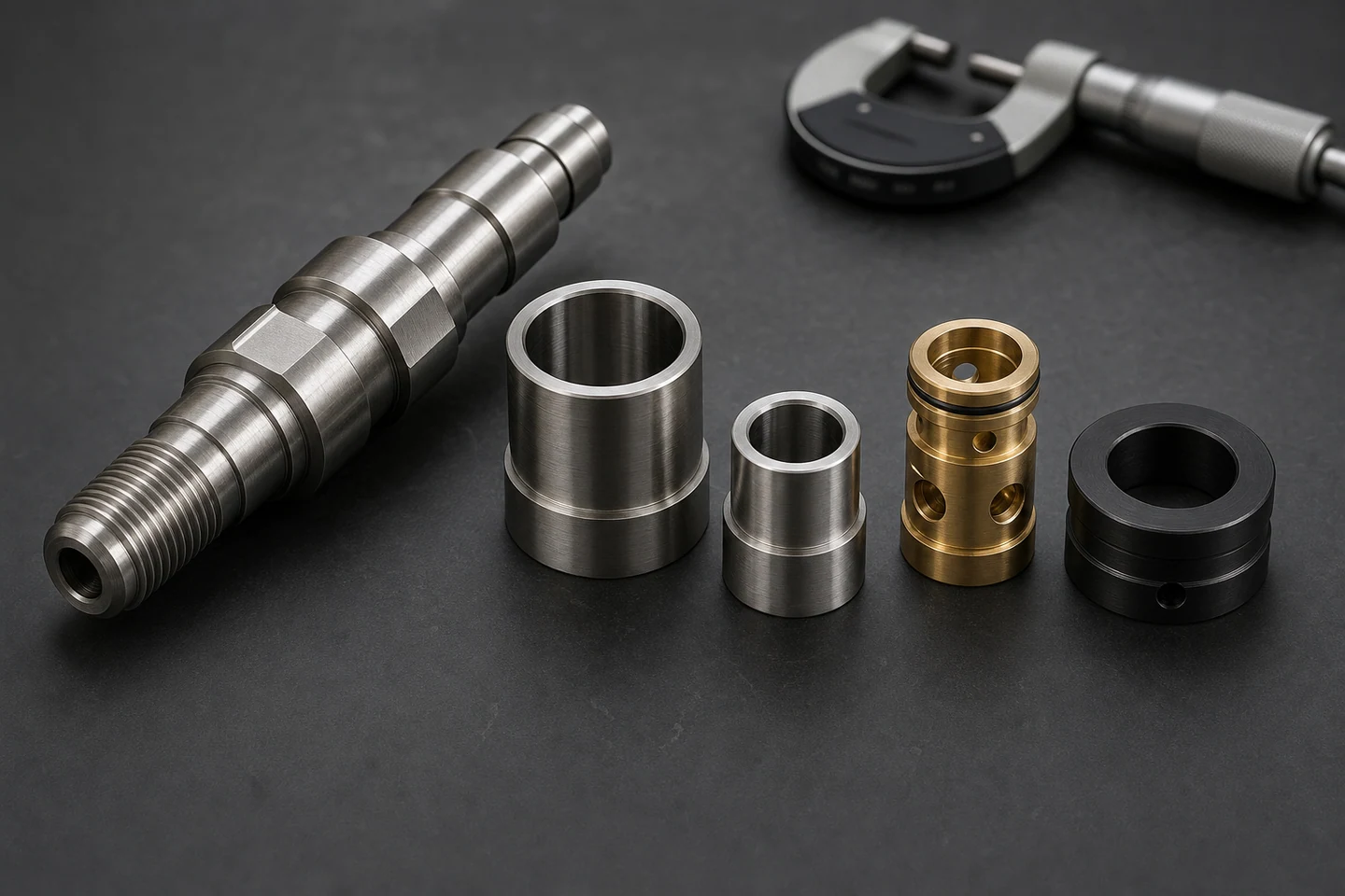
Engineering Specifications
CNC turning planning specs
These values are early planning references. Actual machining plan depends on part diameter, length-to-diameter ratio, material, cross features, tolerance notes, and inspection requirements.
| Specification | Planning range | DFM notes |
|---|---|---|
| Turning configuration | Conventional turning, live tooling, mill-turn and Swiss-type routes across the supplier network. Swiss work commonly runs 2 mm to 32 mm bar, with larger machines reaching about 38 mm. | The project route is selected from diameter, length, axial features, cross features and supplier fit. |
| Part geometry | Round, stepped, bored, threaded, grooved, knurled and turned-milled parts. Swiss guide-bushing support makes length-to-diameter ratios of 20 to 1 routine where conventional turning deflects past about 3 to 1. | Long slender shafts may require support strategy review to control deflection and runout. |
| Materials | Aluminum, stainless steel, alloy steel, brass, copper, POM, PTFE, nylon. Chip behaviour drives the cycle: C360 brass rates 100% on the machinability scale, 303 stainless about 78, 304 about 45. | Material grade, heat treatment, bar size, and machinability are reviewed before quoting. |
| Tolerances and fits | ±0.125 mm (±0.005 in) as standard practice, ±0.025 mm (±0.001 in) on precision diameters, and ±0.013 mm (±0.0005 in) routinely on Swiss-type work. Concentricity within about 0.025 mm across one chucking. | Mark bearing fits, seal diameters, thread class, concentricity, runout, and surface finish requirements. |
| Secondary operations | Threading, tapping, cross drilling, slotting, deburring, polishing and plating by material route. Turned finishes run Ra 1.6 to 3.2 µm, or Ra 0.8 µm with a finishing pass. | Operation order affects burr control, masking, and final inspection access. |
Turning DFM
Design choices that affect turned part routing
Turning works best when the primary geometry is rotational. Complex off-axis details can still be reviewed, but they may shift the part into mill-turn or secondary milling.
Round part geometry
Diameter steps, shoulders, grooves, bores, chamfers, and thread reliefs should be designed with clear access and deburring expectations.
- Add reliefs for threads, shoulders, and grooved features
- Identify surfaces that need specific roughness or polishing
Fit and inspection notes
Turned parts often depend on mating diameters, seal surfaces, bearing seats, thread class, and runout. These requirements should be marked explicitly.
- Attach drawings for concentricity and runout callouts
- Separate cosmetic surfaces from functional bearing surfaces
RFQ Review
Upload CAD for turning route review
Attach the model, drawing, thread callouts, material preference, finish notes, target quantity, and inspection requirements.
Attach turning files in the RFQ form
STEP, STP, IGES, PDF, ZIP. Include thread, fit, runout, and finish notes. Open RFQ formRelated Routes
Compare turning with adjacent CNC routes
Round parts with extensive flat features may become mill-turn parts. Block-like parts should usually start with milling review.
CNC Machining
Review the combined CNC overview for parts that blend milling and turning operations.
CNC Milling
Use milling for block-like parts, pockets, plates, housings, and multi-face prismatic geometry.
5-Axis CNC
Use 5-axis routing for difficult access, compound angles, and sculpted multi-face components.
Material Input
State the preferred grade, acceptable alternatives, finish and any material-document requirements in the RFQ.
Turning FAQ
CNC turning design questions
Prepare the RFQ with drawings for the features that control fit, rotation, sealing, or assembly.