 MAKENEXA
Motion and alignment parts
Shafts, mounts, bearing interfaces and calibration features need datum, fit, load and inspection context.
Industry sourcing decision
Source brackets, housings, end-effectors, fixtures, shafts, guards and integrated custom components for robotics and automation programs. MakeNexa reviews program stage, interfaces, motion, loads, material, process, quantity, inspection and repeat supply before routing the RFQ.
Application context
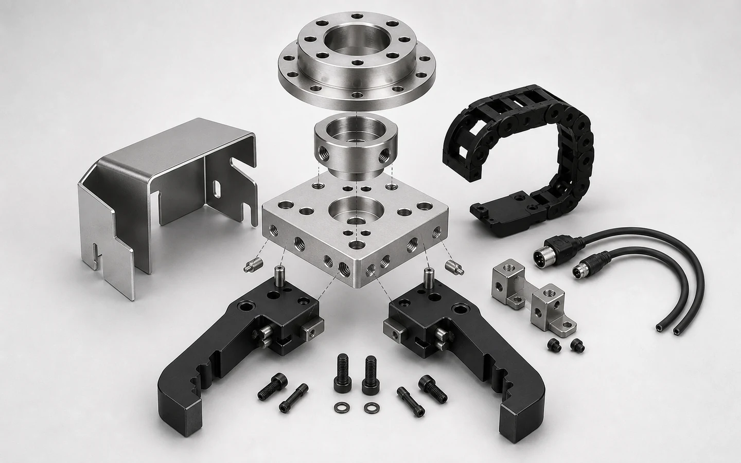
Robotics programs combine mechanical structures, precision motion, sensors, cables, pneumatics, electronics and human interaction. A lightweight arm bracket, wear guide, safety guard and gripper jaw have different manufacturing and release needs even when they belong to one machine. The sourcing package should show controlled interfaces and the subsystem job without disclosing unnecessary proprietary data.
Prototype speed matters, but so do revision control and repeatability when a cell or machine is replicated. MakeNexa compares CNC machining, sheet metal, additive manufacturing, molding, finishes and assembly through its network. The reviewed quote confirms supplier fit, material, tolerance, quantity, inspection, documentation, price and timing; this page does not claim a standard robotics capability envelope.
Typical program needs
Group components by function so the right process and supplier evidence can be selected.
Shafts, mounts, bearing interfaces and calibration features need datum, fit, load and inspection context.
Gripper fingers, nests and tooling often combine fast iteration with repeat location, wear and replaceable interfaces.
Sheet assemblies must support stiffness, access, sensors, cabling, finish and safe human interaction.
Printed or molded ducts, cable guides and protective parts need movement, abrasion, heat and service-life review.
Application risks
A part drawing may not reveal dynamic or maintenance requirements.
Travel, flex, cable motion, tool change and keep-out zones can affect geometry and assembly access.
Moving components may prioritize mass, stiffness and balance differently from static brackets or guards.
Contact surfaces, debris, lubrication, cycle count and field replacement shape material and spare strategy.
Part, software and cell revisions need identifiers that prevent incompatible components from mixing in repeat orders.
Sourcing paths
One subsystem may use several processes with shared datums and finishing requirements.
Machined plates, shafts, mounts and jaws support controlled motion, alignment and fixture relationships.
Frames, guards, trays and enclosures combine cutting, bending, hardware, joining and finish.
Ducts, covers, grippers and cable features may favor rapid iteration or repeat polymer production.
Program decision table
Typical published values for the materials and processes common in robotics and automation work. Achievable results depend on the specific part and supplier route, and the project requirement is confirmed on the reviewed quote rather than from this table.
| Decision area | Typical published value | Review focus |
|---|---|---|
| Moving-mass material | 6061-T6 at 2.70 g/cm³ and 276 MPa / 40 ksi yield against steel at 7.85 g/cm³ — about a third of the mass for the same volume | Every gram on a moving axis costs acceleration and motor size |
| When aluminium is the wrong answer | Modulus is 68.9 GPa against 200 GPa for steel, so a deflection-limited arm gains nothing from aluminium unless the section grows | Whether the part is strength-limited or stiffness-limited |
| Stiffness through geometry | A rib or a formed return adds far more stiffness than a thickness increase, because stiffness follows section depth | Where mass can be removed without losing rigidity |
| Bearing and motor interfaces | Bore fits commonly held to ±0.013 mm and mounting-face flatness to 0.05 mm | The features that actually need precision, marked as such |
| Everything else | ±0.125 mm standard practice covers non-interface geometry | Blanket precision tolerances are the most common avoidable cost |
| Single-setup relationships | Each re-fixture adds roughly 0.05 mm of positional error, so a bearing bore and its mounting face should be cut in one setup | Which relationships must be planned as one operation |
| Covers and guards | 5052-H32 sheet at 193 MPa / 28 ksi yield bends at roughly 1 times material thickness; 6061-T6 cracks below 2 to 3 times | Formed parts move to 5052, machined parts stay on 6061 |
| Cycle life | A part on a moving axis sees millions of cycles; sharp internal corners and engraved marks are fatigue initiation sites | Radii specified, and marking kept off loaded surfaces |
| Finish and grounding | Anodize at 5 to 25 µm insulates; chem film under 1 µm conducts | Every grounding and bonding path identified |
| Fastener interfaces | Threaded inserts in plastic parts need at least 1.5 mm of surrounding material; self-clinching hardware in sheet needs a published minimum thickness around 0.8 mm for M3 | Whether the chosen material and gauge support the hardware |
| Replacement and spares | A spare made two years later from an uncontrolled file is not the same part | Revision control on every part intended for repeat supply |
| Mixed-process assemblies | Machined, sheet, turned and finished components commonly quote together as one route | The interfaces between processes stated, not just the parts |
Industry RFQ inputs
Share the controlled subsystem context needed for routing without overexposing confidential design data.
Complete packages move faster: revision-matched CAD, critical dimensions, quantity and material notes are enough to open engineering review across the network.
Get a QuotePart and assembly models with revision-matched drawings
Subsystem function, mating interfaces, datums and access constraints
Loads, motion, cycles, wear, environment and service conditions
Material, process, finish and permitted-alternative requirements
Prototype, repeat-machine, spare and revision quantity context
Inspection, assembly checks, labeling, packaging and delivery needs
Questions before routing
These answers prepare the request; the reviewed quote controls project-specific commitments.
Both route through the network, and the economics invert between them. At 1 to 10 parts setup dominates so completely that the second part costs a fraction of the first; by a few hundred, per-part cycle time dominates and dedicated fixturing repeating within about 0.01 to 0.02 mm pays back. That changes supplier fit, which tolerances are worth holding and the price basis. What stays constant is where precision belongs — bearing bores at ±0.013 mm and motor faces at 0.05 mm flatness, with everything else at ±0.125 mm standard practice. State the quantity and whether repeat releases are expected.
Sharing the assembly as reference geometry helps considerably, because most robotics part questions are interface questions — which bore carries a bearing, which face locates a motor, which relationships must hold in one setup. Without that context a supplier cannot see that a ±0.125 mm feature and a ±0.013 mm feature sit on the same part. Mark which components are in scope and which are reference only.
By revision, and it matters more on spares than on first builds. A replacement made two years later from an informally updated model is not the same part, and the failure shows up as an assembly that no longer fits. Put a controlled revision identifier on the model and drawing, state the change authority, and state which characteristics must match the original — including finish, since anodize at 5 to 25 µm and powder at 50 to 100 µm per surface change fits.
Yes, and it usually gives a better result than quoting parts separately, because the interfaces are where the problems live. A machined mount, a formed 5052 cover and a turned shaft that must all assemble need their tolerances reviewed against each other rather than individually. State the assembly context and mark the mating interfaces.
Far fewer than most drawings suggest. Bearing bores and motor mounting faces commonly need ±0.013 mm and 0.05 mm flatness respectively; almost everything else works fine at the ±0.125 mm standard practice. The relationships matter more than the individual numbers: a bore and its mounting face cut in one setup hold their perpendicularity far more cheaply than the same two features split across two setups, which adds roughly 0.05 mm on its own.
Next step
Send the application context with the controlled part package. MakeNexa routes capable suppliers from a global network covering competitor-class process categories, then returns a prepared quote or focused clarification for your revision.