 MAKENEXA
Provide tool and inspection access
Review deep pockets, hidden faces, cross holes, undercuts and internal corners from the directions a tool and measurement method can actually reach.
Engineering design resource
Use this guide to make CNC parts easier to interpret, route, inspect and quote. It focuses on access, workholding, datums, internal features, tolerances, threads, edges, material, finishing and drawing control rather than universal design limits.
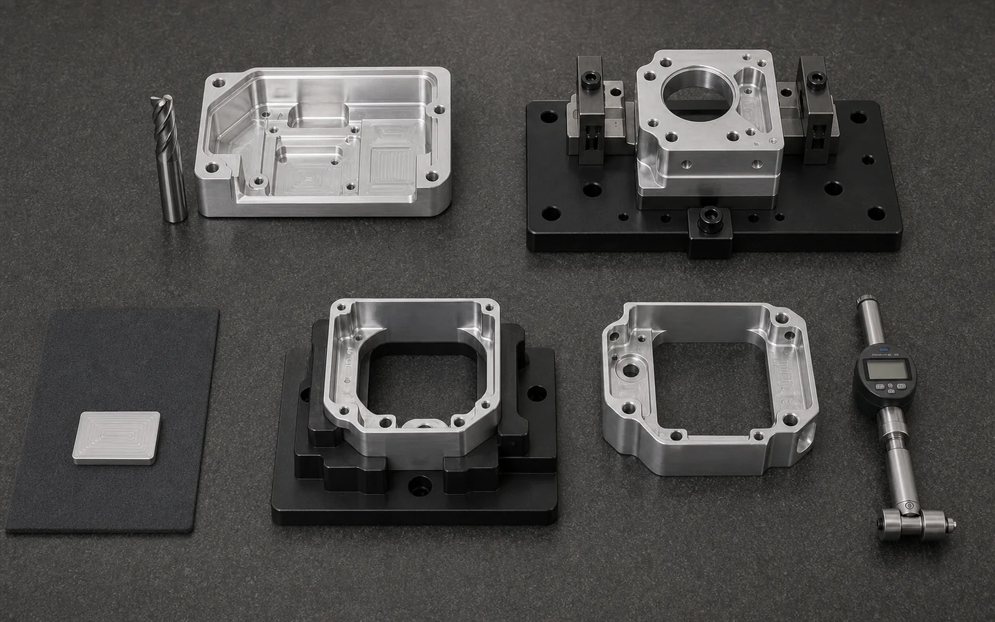
Use this guide
A machine can only reach, hold and inspect the geometry through a real setup. Deep cavities, thin walls, hidden corners, unnecessary small radii, long tools, inaccessible cross holes and over-controlled surfaces can add setups or make the acceptance plan unclear. Good design guidance explains why those features matter without pretending that one numeric rule applies across every size, material and supplier.
Start from part function and identify the datums, interfaces and surfaces that control it. Allow the RFQ review to compare milling, turning, 5-axis, mill-turn, secondary operations or a design adjustment. The reviewed quote should record the chosen assumptions, not silently replace the drawing.
Design priorities
Use these prompts during design review, then confirm project-specific limits with the manufacturing route.
Review deep pockets, hidden faces, cross holes, undercuts and internal corners from the directions a tool and measurement method can actually reach.
Leave practical datum and clamping surfaces, and consider how thin or finished areas will be protected through each setup.
Internal radii come from real tools. Control only the corner or mating geometry that affects function, and allow review of reliefs or larger radii elsewhere.
Rotational bases may favor turning; pockets, planar datums and off-axis features may favor milling or a combined route.
Common review gaps
Most problems come from unclear acceptance or conflicting files, not from missing marketing specifications.
Apply tighter controls to the interfaces that need them and define datums and fits; broad default tightness increases effort without clarifying function.
Identify standard, size, class, depth, handedness, insert and gauge expectations, especially for blind or cross-intersecting threads.
Distinguish a general safe edge from functional chamfers, sealing edges, burr-sensitive passages and cosmetic boundaries.
Keep revision and dimensional authority explicit. Resolve conflicts before quote or list the exact interpretation engineering should review.
Practical choices
Geometry can suggest a process without locking the supplier before review.
Suitable for many prismatic parts when accessible datums and setup transfers can maintain the required relationships.
Useful when the primary geometry is rotational and off-axis features can be completed within a coherent setup strategy.
Useful when feature access, datum transfers, complex surfaces or secondary operations justify a more capable route.
Design decision table
Typical published design practice for CNC machined parts. Achievable geometry depends on material, machine and workholding, and the project requirement is confirmed on the reviewed quote rather than from this table.
| Design topic | Typical published value | Useful RFQ output |
|---|---|---|
| Internal corner radius | Set by the cutter: a Ø6 mm end mill leaves a 3 mm radius, and a 1 mm radius needs a Ø2 mm tool running slowly | Design the largest radius the function allows — it is free money |
| Pocket depth | Depth up to about 4 times the cutter diameter is routine; beyond that deflection and chatter force slow passes | Whether a deep pocket can be opened up or split |
| Minimum wall | About 0.8 mm in metal and 1.0 mm in plastic before deflection under cutting load dominates | Which walls are thin, so workholding can be planned |
| Hole depth | Standard drilling to about 5 times diameter; deeper needs peck cycles or gun drilling | Whether a deep hole justifies a different process |
| Thread depth | Useful engagement runs to about 2 times the nominal diameter | An M6 thread 30 mm deep is cost without strength |
| Minimum feature size | Features down to about 0.5 mm are practical with small tooling at reduced feeds | Where micro-features justify the slower cycle |
| Standard tolerance | ±0.125 mm (±0.005 in) as standard practice | The block value on the drawing |
| Precision tolerance | ±0.025 mm (±0.001 in) on named features only | Which few features carry the function |
| Setup-to-setup error | Each re-fixture adds roughly 0.05 mm of positional error between faces | Relationships tighter than that planned as one setup |
| Surface finish | Ra 1.6 to 3.2 µm as machined; Ra 0.8 µm with a dedicated finishing pass | Call roughness only on functional surfaces |
| Undercuts and internal geometry | Anything a cutter cannot reach is not machinable, however simple it looks in CAD | Whether the part needs splitting or a different process |
| Finishing allowance | Anodize at 5 to 25 µm, powder at 50 to 100 µm per surface, plating at its full thickness | Which dimensions apply before or after finishing |
Turn the guide into an RFQ
A complete package lets the supplier ask focused questions instead of reconstructing design intent.
Complete packages move faster: revision-matched CAD, critical dimensions, quantity and material notes are enough to open engineering review across the network.
Get a QuoteOne current 3D model and revision-matched drawing
Functional datums, mating context and critical interfaces
Material grade, condition, permitted alternatives and records
Threads, inserts, edge conditions, passages and cleanliness
Heat treatment, finish, masking and final inspection condition
Quantity, program stage, delivery context and focused questions
Questions before routing
These answers prepare the request; the reviewed quote controls project-specific commitments.
Around 0.5 mm is practical with small tooling at reduced feeds, but the more useful number is the internal corner radius, because it is set by the cutter rather than chosen. A 1 mm internal radius requires a Ø2 mm end mill that removes material slowly and breaks easily; a 3 mm radius lets a Ø6 mm tool do the work. Designing the largest radius the function allows is one of the few free cost reductions available.
The model defines geometry; it does not define acceptance. Nothing in a solid body states that one bore is ±0.025 mm while the outline is ±0.125 mm, that one face needs Ra 0.8 µm, which edges must stay sharp, what material and condition apply, or whether dimensions are before or after a 5 to 25 µm anodize. A drawing is the controlled place for those, and ASME Y14.41 covers the case where the model itself is meant to carry them.
No. Five-axis reduces setups, which matters because each re-fixture adds roughly 0.05 mm of positional error between faces — but it does not remove the other constraints. Deep pockets past about 4 times cutter diameter still deflect, walls under 0.8 mm still move under cutting load, and internal radii are still set by the tool. Design for the geometry rather than for the machine, and mark the relationships that must hold in one setup.
Send the model early with the functional intent — manufacturability review happens as part of the RFQ, and on a first quote it is often worth more than the price. Suppliers routinely find what a drawing does not mark: a wall under 0.8 mm that deflects under cutting load, an internal radius below 1 mm forcing a Ø2 mm cutter that removes material slowly, a pocket past about 4 times cutter diameter, a relationship split across two setups and so carrying roughly 0.05 mm of extra positional error, or a cross-hole burr nothing can reach. Marking which features are functional is what makes that feedback specific rather than generic.
Three, consistently. Deep narrow pockets — past about 4 times the cutter diameter, deflection forces slow passes with small tools. Small internal radii — 1 mm requires a Ø2 mm cutter where 3 mm lets a Ø6 mm tool work. And blanket tolerances or finishes: applying ±0.025 mm or Ra 0.8 µm across a whole part prices every dimension as precision work to buy accuracy on surfaces that never touch anything.
Next step
Apply the guide to a real drawing and RFQ package. MakeNexa routes capable suppliers from a global network covering competitor-class process categories, then returns a prepared quote or focused clarification for your revision.