 MAKENEXA
Broad thin-walled structures
Panels, covers, guards, ducts and enclosures often align with sheet stock, bends and joined subcomponents. Define bend access, seams, hardware, edge state and appearance zones for the complete assembly.
Engineering design resource
If you are choosing sheet metal vs CNC machining, start from the finished envelope—not which process sounds cheaper. Sheet metal cuts, bends and joins constant-thickness stock; CNC removes material for three-dimensional features and tight interfaces. Walls, bends, hardware, quantity and change risk usually decide. State the functional envelope, then upload CAD so MakeNexa can review the route.
Use this guide
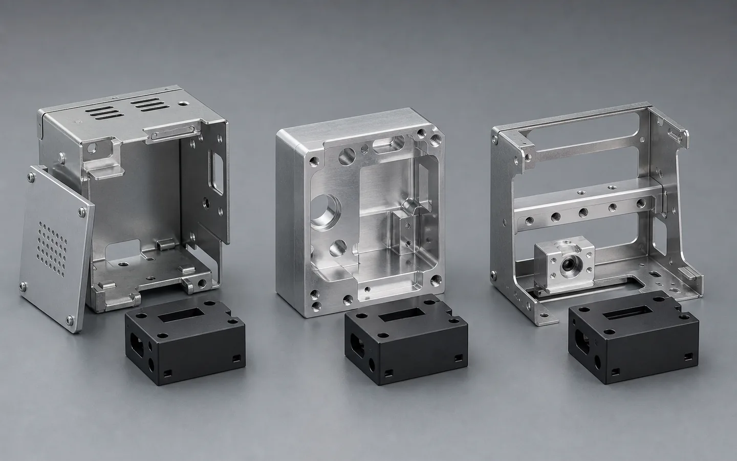
Sheet metal is often a strong route for enclosures, guards, brackets, panels and chassis that can be unfolded into manufacturable blanks and rebuilt through bends, seams or hardware. It can create broad thin-walled structures with efficient material use, but bend access, bend radii, grain direction, corner relief, springback, weld distortion and stack-up across joined pieces become design inputs. Local thickness is usually tied to available sheet gauge unless doublers, formed features or attached components are added.
CNC machining is often a strong route for compact parts with pockets, bores, datum faces, thick sections, complex local features or controlled interfaces in multiple orientations. It can create integral geometry from one stock form, but tool reach, setups, workholding, deep cavities, thin-wall distortion and removed material influence the route. A hybrid design can use formed panels with machined blocks, rails, bosses or interface plates. Compare the complete assembled function and evidence needs rather than forcing one process across every feature.
Design priorities
Stock form and feature creation should align with the dominant structure while preserving critical interfaces.
Panels, covers, guards, ducts and enclosures often align with sheet stock, bends and joined subcomponents. Define bend access, seams, hardware, edge state and appearance zones for the complete assembly.
Deep pockets, precision bores, thick bosses, intersecting passages and multi-face datum structures often align with machining. Review cutter access, stock size, setup transfer, wall stiffness and final inspection access.
Machined inserts, rails, bearing blocks and mounting pads can add local precision to a fabricated structure. Define how interfaces locate, join and remain accessible through welding, coating and final assembly.
Both processes can support prototypes and repeat quantities, but design changes affect blanks, bends, fixtures, programs and assemblies differently. State the expected learning objective and which elements are likely to change.
Common review gaps
The same function may need different geometry in each route, so a direct file-to-file quotation can hide redesign needs.
A solid pocketed part rarely becomes sheet metal by replacing walls with one thickness. It may need tabs, flanges, seams, fasteners, access features and separate interface pieces, with a new tolerance stack.
Machining every panel, flange and cavity from solid stock may create deep access, thin-wall, workholding and material-removal challenges. Preserve the function while redesigning the architecture for the route.
Bend location, formed angles, welded assemblies, machined datums and bore relationships have different process behaviors. Allocate tight controls to functional interfaces and choose post-process machining where the assembly needs it.
Machining marks, cut edges, bend witness, weld cleanup, grain direction, coatings and masked contacts shape acceptance. Define cosmetic zones, protected surfaces and the state in which dimensions apply.
Practical choices
Each option should be evaluated as a manufacturable design with its own interfaces and validation plan.
Use cut and formed stock when broad walls, panels, bends and assembled construction dominate. Design reliefs, seams, hardware, access, finish and stack-up around available material and forming constraints.
Use machined stock when integral three-dimensional geometry, controlled bores, datum faces, local thickness or multi-face features dominate. Design for cutter access, support, setup and inspection.
Combine formed structures with machined interface pieces when the assembly needs broad lightweight coverage and concentrated precision. Control joining, location, distortion, finish sequence and replacement strategy across components.
Design decision table
Typical published capability for press-brake fabrication against CNC machining. Achievable results depend on material, geometry and supplier, and the project requirement is confirmed on the reviewed quote rather than from this table.
| Decision factor | Sheet metal direction | CNC machining direction |
|---|---|---|
| Tolerance on a flat feature | About ±0.13 mm on a laser-cut profile | ±0.125 mm standard practice, ±0.025 mm on named precision features |
| Tolerance across a bend | Commonly ±0.5 mm and looser, with bend angle at ±1° | Unaffected — machined geometry carries no bend chain |
| Angular accuracy | ±1° is standard; on a 300 mm panel that is about 5 mm at the free edge | Machined angles hold to the general tolerance |
| Material efficiency | Near-net: a formed part uses roughly the sheet area of its flat pattern | Subtractive: a 50 mm bar turned to 20 mm removes about 84% of its volume as chip |
| Stiffness for the mass | A 1.5 mm formed panel with returns can outperform a much thicker flat machined plate, because stiffness follows section depth | Stiffness comes from thickness, which costs material and machining time |
| Common gauges | 1.0 mm, 1.5 mm and 2.0 mm cover most enclosure and bracket work | Any thickness the stock and the machine allow |
| Minimum bend radius | About 1 times material thickness in 5052-H32; 2 to 3 times in 6061-T6 | Not applicable |
| Hole to bend distance | At least 2.5 times material thickness plus the bend radius | Not applicable |
| Feature freedom | Constant thickness only; no pockets, bosses or varying wall | Any geometry a cutter can reach, with internal radii set by the tool |
| Surface finish | Mill finish or as-cut, near Ra 3.2 µm at the edge | Ra 1.6 to 3.2 µm as machined, Ra 0.8 µm with a finishing pass |
| Setup economics | Standard press-brake tooling covers most work, so low quantities scale gracefully | Setup dominates below about 10 parts; fixturing pays back over a few hundred |
| Where each wins outright | Enclosures, brackets, panels and anything whose function is a folded constant-thickness shape | Precision interfaces, bearing bores, sealing faces and varying-section geometry |
Turn the guide into an RFQ
Provide the functional envelope and redesign freedom so both routes can be compared on equivalent requirements.
Complete packages move faster: revision-matched CAD, critical dimensions, quantity and material notes are enough to open engineering review across the network.
Get a QuoteSubmit the controlled model, drawing, revision, assembly and mating context
Define loads, stiffness, mass, environment, access, sealing and appearance needs
Mark critical bores, datums, bends, seams, welds, hardware and removable panels
State preferred materials, gauges or stock forms, permitted substitutions and grain needs
Specify tolerance allocation, final machining, finish, masking, inspection and documentation
List prototype and repeat quantities, expected design changes, assembly scope and redesign authority
Questions before routing
These answers prepare the request; the reviewed quote controls project-specific commitments.
For a part whose function is a folded constant-thickness shape, almost always — it is near-net, uses standard tooling and scales gracefully at low quantity. But the comparison breaks down when the part needs precision interfaces. Sheet holds about ±0.13 mm on a flat cut feature and commonly ±0.5 mm across a bend with ±1° angular tolerance; a machined interface holds ±0.125 mm as standard practice and ±0.025 mm where needed.
Rarely as-is. A machined design typically carries varying wall thickness, pockets, bosses and internal radii that sheet cannot reproduce — sheet is constant thickness by definition. The conversion also introduces new rules: a minimum inside bend radius of about 1 times thickness in 5052, holes at least 2.5 times thickness plus the radius from a bend, and tolerance chains that accumulate across bends. It is a redesign, and usually a worthwhile one.
Machining, particularly across features. Sheet holds a laser-cut flat profile to about ±0.13 mm, which is competitive, but every bend adds error — commonly ±0.5 mm on a dimension across a bend and ±1° on the angle, which is about 5 mm at the free edge of a 300 mm panel. Machining carries no equivalent chain. The practical design answer is to keep precision interfaces on one face, or to machine them into a fabricated part afterward.
Whenever a folded part needs a precision interface. A fabricated bracket with a machined bearing pad, or a sheet-metal chassis with machined mounting faces, gets sheet's material efficiency and machining's ±0.025 mm where it matters. The sequence is the design decision: machine after forming and after any welding, since a welded assembly moves 1 mm per metre and more. State which dimensions apply at which stage.
Look at whether the function needs varying section. If the bracket is a folded shape carrying a bolt pattern, sheet is cheaper, lighter and stiffer for its mass — a 1.5 mm formed panel with returns can outperform a much thicker flat plate, because stiffness follows section depth. If it carries a bearing bore, a sealing face or interfaces that must hold tighter than about ±0.5 mm relative to each other, machine it or add a machined operation.
Next step
Apply the guide to a real drawing and RFQ package. MakeNexa routes capable suppliers from a global network covering competitor-class process categories, then returns a prepared quote or focused clarification for your revision.