 MAKENEXA
Process and access
Check cutting-tool reach, bend access, support removal, powder escape, mold movement, ejectability and workholding surfaces for the routes under consideration. Identify features that may need a different operation.
Engineering design resource
A useful DFM review connects the design to a plausible manufacturing route without pretending that one rule fits machining, fabrication, additive manufacturing and molding. Use this checklist to expose the decisions and open questions engineering needs before routing and quote preparation.
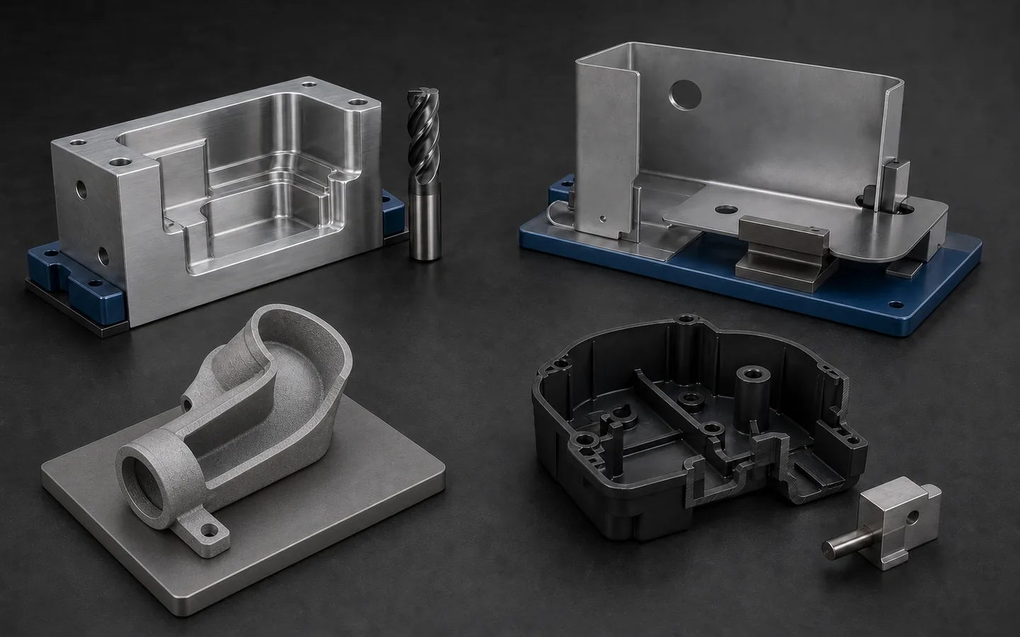
Use this guide
Start by naming the likely route and the job the part performs. The same wall, pocket, hole or corner can behave differently when it is cut from stock, formed from sheet, built layer by layer or created in a mold. Review tool or process access, material form, orientation, section changes and the surfaces needed for locating and inspection. If the route is still open, describe the functional priorities and permitted alternatives rather than forcing a process from an early assumption.
Then follow the part beyond its primary operation. Heat treatment, finishing, hardware, joining, assembly, cleaning, marking, inspection and packaging can introduce access restrictions or change the final condition. A good pre-RFQ review records which requirements are fixed, which are preferences and which need human engineering assessment. MakeNexa provides assisted review and supplier routing; it does not represent the submission as automated DFM, instant manufacturability analysis or a production commitment.
Design priorities
A strong design keeps the primary process, downstream operations and acceptance plan compatible with one another.
Check cutting-tool reach, bend access, support removal, powder escape, mold movement, ejectability and workholding surfaces for the routes under consideration. Identify features that may need a different operation.
Confirm material condition, stock form, sheet thickness, resin or powder route and allowed alternatives. Consider directional behavior, availability, stability and how the selected form affects waste or tooling.
Review thin sections, abrupt thickness changes, deep features, large flat areas, long slender geometry and interrupted cuts for distortion, support, fill, cooling or handling risk.
Sequence heat treatment, coating, machining, hardware, joining and assembly so critical surfaces remain accessible and final dimensions, appearance and interfaces can still be controlled.
Common review gaps
These patterns often transfer risk from the drawing into the supplier's unstated assumptions.
A modeled pocket, undercut, internal channel or fastener location may lack a practical tool path, forming sequence, escape route, mold action or assembly direction. Show the required function if geometry may change.
An alloy or polymer family alone may not define temper, grade, fill, stock form, color or permitted equivalent. State the property or certification need behind the selection and whether alternatives can be quoted.
Very thin walls, flexible clips, broad panels and post-treatment sections may move between operations or during inspection. Connect controls to final function and a realistic locating condition.
Coating can close clearances, hardware can block finishing, welds can distort machined datums and packaging can damage cosmetic surfaces. Review the complete operation sequence before locking acceptance.
Practical choices
Engineering can evaluate options more effectively when the fixed function and negotiable implementation are separated.
Hold the interface, load, environmental condition, appearance zone or regulatory input that the design must satisfy, while allowing the route or local geometry to be reviewed.
Permit an alternate process, stock form, construction or sequence when it preserves the controlled outcome. Require the quote to identify changes, exclusions and evidence differences.
For early programs, separate a learning build from production-intent tooling, finish or inspection. Record which characteristics are being evaluated before imposing repeat-production controls.
Design decision table
Typical published design limits across the common processes, given so an issue can be routed to the guidance that answers it. Achievable geometry depends on material, machine and supplier, and the project requirement is confirmed on the reviewed quote rather than from this table.
| Review area | Typical published limit | Likely deeper route |
|---|---|---|
| Machined internal radii | Set by the cutter: 1 mm needs a Ø2 mm tool; 3 mm lets a Ø6 mm tool work several times faster | CNC machining design guide |
| Machined pocket depth | Routine to about 4 times the cutter diameter before deflection dominates | CNC machining design guide |
| Machined wall thickness | About 0.8 mm in metal, 1.0 mm in plastic, before cutting load deflects it | CNC machining design guide |
| Sheet bend radius | About 1 times thickness in 5052-H32; 2 to 3 times in 6061-T6 | Sheet metal design guide |
| Sheet hole to bend | At least 2.5 times thickness plus the bend radius | Sheet metal design guide |
| Moulded wall | 1.0 mm to 3.0 mm uniform, within about 25% of nominal, with ribs at 50 to 60% of wall | Injection molding design guide |
| Moulded draft | 1° to 2° minimum on unfilled resins, 3° to 5° on textured | Injection molding design guide |
| Additive overhang | Self-supporting to roughly 45° from vertical in both polymer and metal | 3D printing route pages |
| Additive powder escape | At least two holes of 4 to 5 mm per enclosed volume; metal channels below about 0.5 mm cannot be cleared | 3D printing route pages |
| Tolerance realism | ±0.125 mm machining standard, ±0.1 mm moulding, ±0.2 to ±0.3 mm printing, ±0.5 mm across a sheet bend | Tolerance planning checklist |
| Finishing allowance | Anodize 5 to 25 µm, powder 50 to 100 µm per surface, plating its full thickness, electropolish removing 10 to 40 µm | Surface finish selection guide |
| Interfaces and datums | Each machining re-fixture adds roughly 0.05 mm; welding moves an assembly 1 mm per metre and more | Tolerance planning and drawing review |
Turn the guide into an RFQ
Send the open engineering questions with the controlled package rather than resolving them through hidden assumptions.
Complete packages move faster: revision-matched CAD, critical dimensions, quantity and material notes are enough to open engineering review across the network.
Get a QuoteState the part function, project stage, likely route and any process alternatives that are allowed
Check tool, forming, build, mold and assembly access for every enclosed or obstructed feature
Define material grade or performance need, starting form, condition and permitted substitutions
Review thin, deep, long, flat or abrupt geometry for support, stability, fill, cooling or handling risk
Sequence heat treatment, finishing, hardware, joining, marking, cleaning and assembly
Identify critical characteristics, inspection access, sample scope, packaging and protected surfaces
Questions before routing
These answers prepare the request; the reviewed quote controls project-specific commitments.
It happens as part of the RFQ, carried out against the actual supplier route rather than by an automatic checker — which matters because most real manufacturability issues are contextual. Whether a 1 mm internal radius is worth its Ø2 mm cutter depends on quantity; whether a wall under 0.8 mm is a problem depends on how it is held; whether a ±0.025 mm relationship is expensive depends on whether it can be cut in one setup. Send the model early with the functional intent and mark which features are functional, and the review comes back while changes are still cheap.
Not necessarily, but the design usually implies one, and the design limits differ sharply. A part designed with 1.0 mm to 3.0 mm uniform walls and 1° to 2° draft is a moulded part; one with varying section and pockets is machined; one with constant thickness and folds is sheet. If the process is genuinely open, state the function, quantity and requirements and let the route be reviewed — but expect a redesign if the geometry suits a different one.
Very few, and that is the point of naming the process. Three that travel: tolerance should follow function rather than being applied uniformly, since ±0.125 mm costs nothing in machining while ±0.025 mm does; finishing changes dimensions by 5 to 100 µm depending on the route, so the drawing must say before or after; and features nothing touches do not need callouts. Everything else — radii, walls, draft, overhangs — is process-specific.
Fix the obvious cost drivers, then quote. Enlarging internal radii from 1 mm to 3 mm, reducing pocket depth below about 4 times cutter diameter, and moving a blanket ±0.025 mm back to ±0.125 mm with tight bands only where needed are all cheap changes with large effects. Beyond that, quoting early is usually better than iterating alone — the supplier review will find things the checklist does not.
Tolerances and finishes applied uniformly rather than functionally. A drawing with ±0.025 mm on every dimension and Ra 0.8 µm on every surface prices the whole part as precision work to buy accuracy on faces nothing touches — and it is usually the fastest saving available. The second most common is not stating whether dimensions apply before or after a finish that adds 5 to 100 µm.
Next step
Apply the guide to a real drawing and RFQ package. MakeNexa routes capable suppliers from a global network covering competitor-class process categories, then returns a prepared quote or focused clarification for your revision.