 MAKENEXA
Component and board interfaces
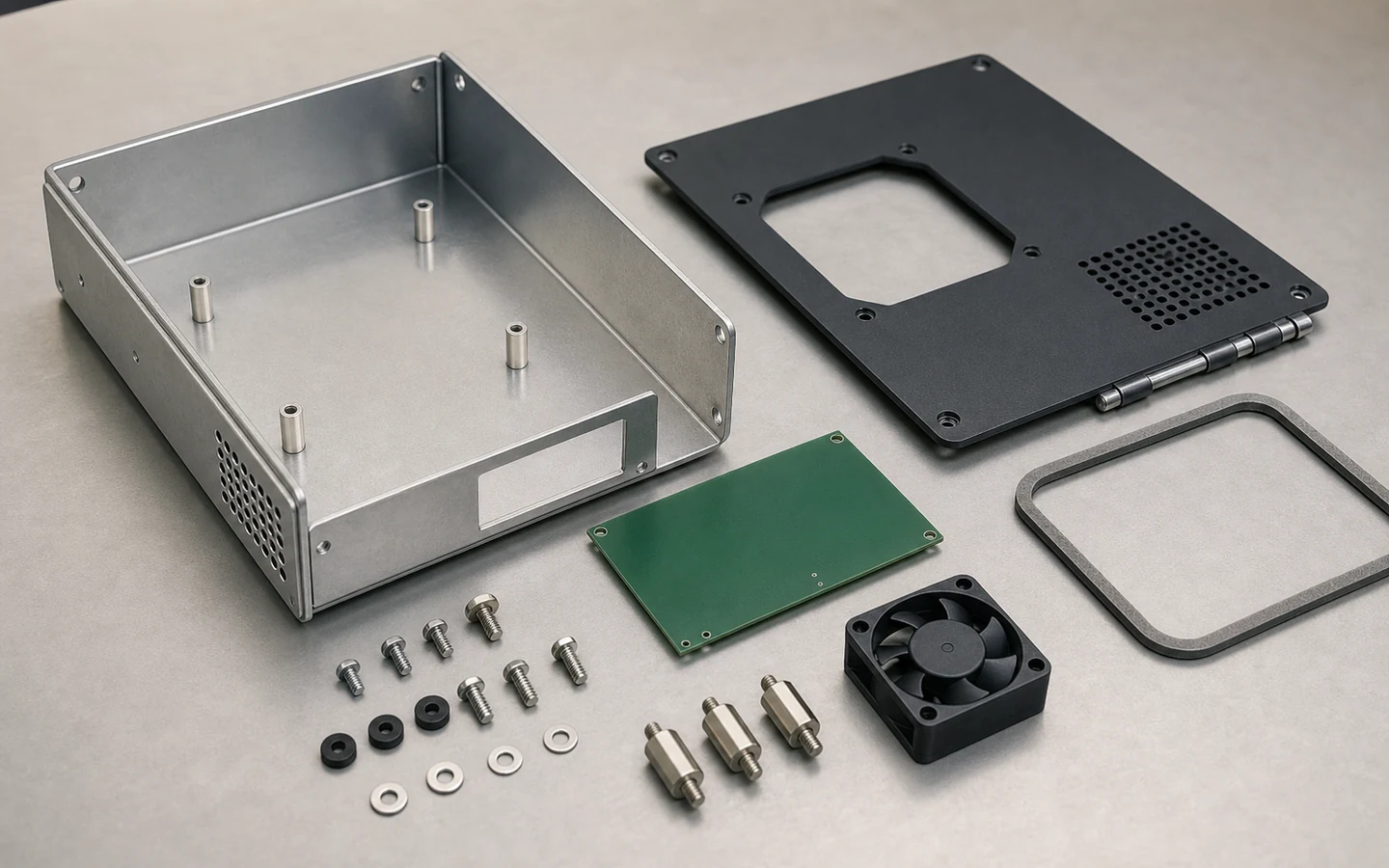
Mounting patterns, standoffs, rails, connector cutouts and keep-out zones should match the controlled assembly revision.
Manufacturing service decision
Source equipment housings, electronics enclosures, control boxes, covers and multi-part sheet assemblies through MakeNexa. Engineering reviews internal components, interfaces, access, ventilation, ingress considerations, joining, finish and quantity before routing the enclosure to a suitable supplier.
Route decision
An enclosure must locate and protect what sits inside while remaining manufacturable, serviceable and inspectable. Board mounts, displays, connectors, hinges, seals, vents, cable paths and fasteners compete for space near bends and seams. A dimensionally correct shell can still fail if a tool cannot reach a fastener, a door collides with a connector, or coating closes a grounding interface.
MakeNexa reviews the enclosure-level model, part drawings and a simple assembly description together. The route may combine cutting, forming, hardware insertion, welding, grinding, coating, printing and final assembly. Buyers should distinguish environmental targets from formal certification claims and identify which interfaces, appearance zones and tests are required. Supplier fit, process sequence, achievable controls, price and lead time are confirmed only after RFQ review.
Best-fit parts and programs
Start with what the housing must hold, expose, protect and allow a person to service.
Mounting patterns, standoffs, rails, connector cutouts and keep-out zones should match the controlled assembly revision.
Hinges, latches, removable panels and tool access need clearance through the complete opening and closing path.
Ventilation, fans, filters, drain paths and seals should reflect the real thermal and environmental problem.
Displays, labels, indicators, handles, exposed edges and cosmetic zones affect fabrication, finishing and final assembly.
Feasibility checks
These conflicts often appear only when parts, hardware and finish are reviewed as one stack.
Multiple bends, welded seams and panel interfaces can accumulate variation at doors, connectors and mounting points.
Studs, nuts, inserts and screws need installation and service clearance after adjacent flanges and components are present.
Grounding points, tight fits, threads, hinges and gasket lands may require masking or post-finish operations.
A gasketed design does not automatically carry an IP or NEMA rating; requested tests and certification responsibilities must be explicit.
Route options
Part count, access, appearance and quantity influence whether the enclosure is joined, modular or assembled with fasteners.
Useful when bend access, material utilization and component installation support a consolidated shell.
Considered for rigid frames, sealed corners or geometries that cannot be formed cleanly from one blank.
Separate panels can improve service, finishing, shipping or revision control when interfaces are defined.
Decision comparison
Typical published practice for fabricated sheet-metal enclosures. Achievable tolerances and finish depend on size, material, construction and the supplier's equipment, and the project requirement is confirmed on the reviewed quote rather than from this table.
| Decision area | Typical published value | Review focus |
|---|---|---|
| Overall dimensional tolerance | Commonly ±0.5 mm and looser on a large fabricated enclosure — tolerances accumulate across every bend and joint | Which few dimensions are functional, measured from a stated datum |
| Panel-to-panel gap | Commonly 0.5 to 1.5 mm designed clearance on a hinged or removable panel | Too tight and the panel binds after finishing adds 50 to 100 µm per surface |
| Bend angle tolerance | Commonly ±1°, which on a 300 mm panel is about 5 mm at the free edge | Why long unsupported panels need a stiffening feature rather than a tighter tolerance |
| Common gauges | 1.0 mm, 1.5 mm and 2.0 mm cover most enclosure work in steel and aluminium | Gauge, hardware minimums and stiffness reviewed together |
| Panel stiffness | A formed return or a swage adds far more stiffness than a gauge increase, because stiffness follows section depth | Whether a large flat panel needs geometry rather than thickness |
| Self-clinching hardware | Requires a minimum sheet thickness and edge distance published by the hardware manufacturer | Whether the chosen gauge supports the hardware at all |
| Welded construction | Welding an enclosure distorts it well past machining tolerance; critical interfaces are machined afterward | Which dimensions apply before welding and which after |
| Sealing and gasket compression | A gasket needs a stated compression range and a flange flat enough to deliver it across the whole perimeter | Flatness on the sealing face rather than on the enclosure overall |
| Ingress protection | An IP rating is a tested result on a complete assembly, not a property of a design or a gasket | Who performs the test, on what configuration, and to what acceptance |
| Finishing effect | Powder adds 50 to 100 µm per surface and closes clearances, threads and hinge fits | Which features are masked, and whether gaps allow for the film |
| Cosmetic surfaces | Bend witness marks, weld dressing and grain direction all vary unless specified | Which faces are cosmetic, with a reference where appearance is contractual |
| Grounding and bonding | Powder and anodize both insulate; a bonding path needs a masked contact area or chem film | Every electrical interface identified on the drawing |
Quote inputs
Include enough assembly context to review use, access and finish together.
Complete packages move faster: revision-matched CAD, critical dimensions, quantity and material notes are enough to open engineering review across the network.
Get a QuoteTop-level assembly model plus revision-matched part drawings
Material, thickness and permitted substitutions for every fabricated part
Component, board, connector, hinge, latch and gasket interface data
Weld, hardware, grounding, ventilation and service-access requirements
Finish, masking, markings, cosmetic zones and protected surfaces
Quantity, assembly scope, functional checks, packaging and delivery needs
Questions before routing
These answers prepare the request; the reviewed quote controls project-specific commitments.
Yes — fabrication, hardware installation, finishing and assembly all route through the network, and quoting the whole scope together gives a better result because the operations interact. Hardware minimums depend on gauge, at around 0.8 mm for an M3 clinch nut; welding distorts what was formed; powder at 50 to 100 µm per surface closes the clearances that were designed in; and a 200 °C cure excludes bearings, seals and electronics from going through it. State the full scope including hardware, finish, assembly and any customer-supplied components for supplier fit, price and lead time on the reviewed quote.
Not from the design alone. An ingress protection rating is a tested result on a specific complete assembly in a specific configuration — gasket, fasteners, cable entries, panel flatness and assembly torque all affect it. A design intended to achieve a rating is not the same as a rated enclosure. State whether testing is required, who performs it, on what configuration and to what acceptance, and it is reviewed and confirmed on the quote.
By naming the surfaces and the acceptance basis, not by describing an intent. Bend witness marks appear on the outside of every bend as a matter of process, weld dressing varies, grain direction varies, and powder at 50 to 100 µm per surface highlights rather than hides substrate marks. Mark which faces are cosmetic, supply a controlled reference where appearance is contractual, and state the acceptable variation and viewing condition.
Include them as reference geometry even when they are not supplied, because clearances, cable routing, connector cut-outs, grounding paths and thermal openings are all enclosure decisions. Note that powder coating and anodize both insulate, so any bonding or grounding surface needs masking or a conductive finish such as chem film. State which components are customer-supplied and which are in scope.
Usually accumulated tolerance rather than a fault. Each bend carries commonly ±1° and each dimension across a bend adds its own error, so a large enclosure accumulates several millimetres across a chain of features — on a 300 mm panel, 1° alone is about 5 mm at the free edge. The design answers are a designed gap of 0.5 to 1.5 mm on panel interfaces, slotted mounting holes, and specifying tolerance only on the few interfaces that must fit.
Next step
Send geometry and process requirements for review. MakeNexa routes capable suppliers from a global network covering competitor-class process categories, then returns a prepared quote or focused clarification for your revision.