 MAKENEXA
Internal flow paths
Conformal cooling, manifolds and compact passages may justify additive when build, powder removal, cleaning and inspection are feasible.
Manufacturing service decision
Source metal additive manufacturing for complex prototypes, lightweight structures, consolidated assemblies and selected production components. MakeNexa reviews alloy, geometry, support and removal access, heat treatment, machining, surface, testing and documentation before confirming a route.
Route decision
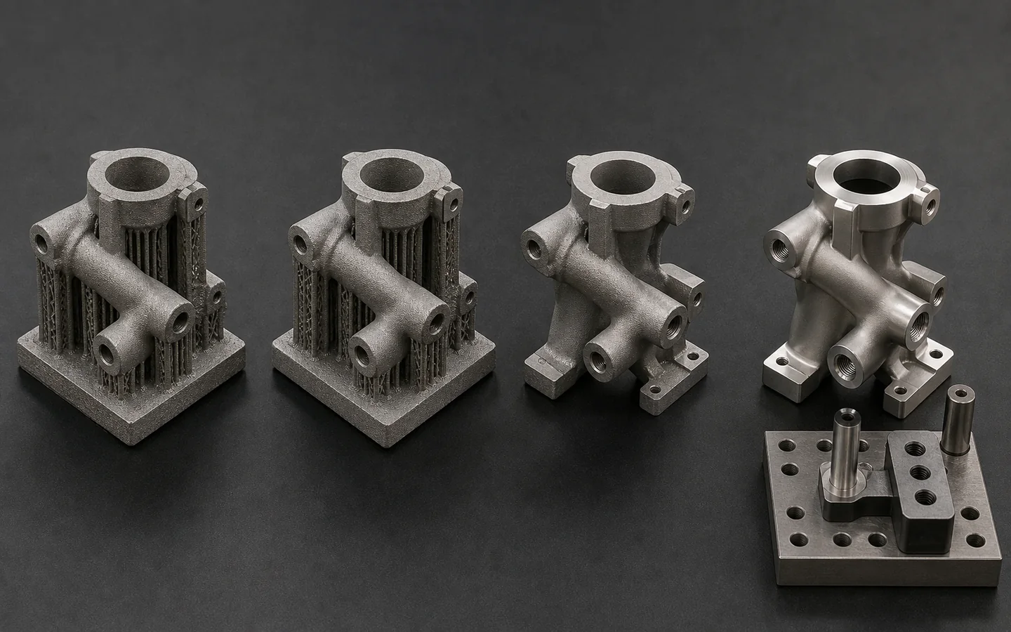
Metal 3D printing can create internal channels, topology-driven shapes and consolidated geometry that is difficult to machine or fabricate conventionally. The printed build is rarely the complete purchasing answer. Supports must be removed, the part may need stress relief or heat treatment, datum surfaces and holes may need machining, and internal quality or material verification may require defined tests.
MakeNexa compares additive routes with CNC machining, casting, fabrication and hybrid sequences. The RFQ should show final geometry and identify machining stock, protected internal passages, surface and roughness needs, material specification, critical loads, documentation and quantity. Build process, powder or wire route, machine, orientation, support strategy, supplier, capability, price and lead time remain project-specific until engineering review is complete.
Best-fit parts and programs
Complexity should create functional or commercial value, not exist only because the process can build it.
Conformal cooling, manifolds and compact passages may justify additive when build, powder removal, cleaning and inspection are feasible.
Multiple components, joints or fasteners may be integrated when service, inspection and failure containment remain acceptable.
Topology-driven or lattice geometry can reduce mass when load cases, surface, cleaning and verification are defined.
Complex parts may avoid tooling or extensive assembly at prototype and selected production volumes after total route cost is compared.
Feasibility checks
The printed shape, final material condition and released component are different stages.
Support access, witness surfaces and removal sequence can affect geometry, finish and downstream machining.
Stress relief, solution treatment, aging or hot isostatic pressing may change shape, properties, cost and documentation.
Sealing faces, precision holes, threads and datum features need accessible stock and a defined final machining plan.
Critical applications may require density, defect, powder-removal, chemical, mechanical or nondestructive test definitions.
Route options
Engineering should compare finished, inspected components rather than printed near-net shapes alone.
Near-net building can be followed by controlled datum creation, bores, threads and sealing-surface machining.
Often clearer for accessible geometry, demanding surfaces, small quantities and alloys readily available in wrought form.
Considered when quantity, scale, internal geometry, material condition, tooling or joining economics favor conventional production.
Decision comparison
Typical published values for laser powder-bed fusion. Achievable accuracy, density and surface depend on alloy, machine, orientation and post-processing, and the project requirement is confirmed on the reviewed quote rather than from this table.
| Decision area | Typical published value | Review focus |
|---|---|---|
| Layer thickness | 0.03 mm is a common production setting, with 0.02 mm for fine detail and 0.06 mm for speed | Build time and cost scale with height, not with part complexity |
| As-built accuracy | Commonly ±0.1 mm or ±0.2% of the nominal, whichever is larger — before any machining | Which features need machining to reach their tolerance |
| As-built surface | Ra 6 to 20 µm on vertical walls, and up to 25 µm and rougher on downward-facing surfaces | Nothing sealing, sliding or mating should be left as built |
| Density | Above 99.5% of wrought density with correct parameters | Whether porosity matters for the load case |
| Minimum wall | About 0.4 mm; thinner walls warp during the build | Whether the design's thin features are printable |
| Self-supporting angle | Overhangs hold to roughly 45° from vertical; below that, supports are required and must be physically removed afterward | Whether supports can be reached at all |
| Support removal | Metal supports are welded to the part and are cut, machined or ground off, leaving witness | Internal supports that cannot be reached make a geometry unbuildable |
| Stress relief | A mandatory heat-treatment step before the part is cut from the build plate; skipping it distorts or cracks the part | A specified operation, not an optional one |
| Powder removal | Internal channels below about 0.5 mm cannot be cleared reliably; enclosed volumes cannot be cleared at all | Every internal passage and its access, stated |
| Build envelope | Common production machines build within about 250 × 250 × 325 mm | Envelope, and whether the part can be split and joined |
| Post-machining | Bores, sealing faces, threads and datums are machined after printing, which needs stock allowance designed in | Which surfaces are printed to final and which are machined |
| Fatigue behaviour | As-built surface roughness and residual porosity both reduce fatigue life; hot isostatic pressing is specified where fatigue governs | Whether the load case is static or cyclic |
Quote inputs
Submit the final component definition and the evidence needed to release it.
Complete packages move faster: revision-matched CAD, critical dimensions, quantity and material notes are enough to open engineering review across the network.
Get a Quote3D model and drawing with final datums and controlled requirements
Alloy, material condition, permitted process routes and records
Load, temperature, pressure, fatigue and service context
Support restrictions, internal passages, cleaning and powder-removal needs
Heat treatment, machining stock, surface, coating and masking
Inspection, testing, documentation, quantity, packaging and delivery
Questions before routing
These answers prepare the request; the reviewed quote controls project-specific commitments.
No, and this is the most common surprise on a first metal additive project. A printed part needs stress relief before it is cut from the build plate, then support removal, then machining on every surface that has a tolerance — as-built accuracy is commonly ±0.1 mm or ±0.2% with Ra 6 to 20 µm surfaces, so nothing sealing, sliding or mating can be left as printed. Design stock allowance into those faces and state which surfaces are printed to final.
With difficulty, which is why the design has to make them verifiable. Channels below about 0.5 mm cannot have their powder cleared reliably, and a fully enclosed volume cannot be cleared at all — trapped powder is both a contamination and a mass problem. Internal surfaces also come out at Ra 20 µm and rougher. Provide channel dimensions, access points, cleanliness and flow requirements, and state the verification method — flow test, CT scan or borescope.
Not generally. Correctly processed parts reach above 99.5% of wrought density and comparable static strength, but fatigue life is usually lower because as-built surface roughness at Ra 6 to 20 µm and residual porosity both act as initiation sites. Hot isostatic pressing and machining the critical surfaces close much of that gap, at cost. Where fatigue governs, state it explicitly so the post-processing route is reviewed rather than assumed.
Most of the time, honestly. Metal additive earns its cost on geometry that cannot be machined — internal conformal channels, consolidated assemblies, topology-optimised structures — or on lead time for a single part in an exotic alloy. For a part that a mill can reach, machining is faster, cheaper, more accurate at ±0.125 mm as standard practice, and better on fatigue. Compare on the geometry, not on the novelty.
Because cost follows build height and machine time rather than part complexity, and then the post-processing adds more. A part occupying 200 mm of build height ties up the machine for that whole height regardless of how little material it contains. On top of that come mandatory stress relief, support removal, machining on every toleranced surface and often hot isostatic pressing. Reducing height and orienting for fewer supports usually cuts cost more than simplifying features.
Next step
Send geometry and process requirements for review. MakeNexa routes capable suppliers from a global network covering competitor-class process categories, then returns a prepared quote or focused clarification for your revision.