 MAKENEXA
Turning-led geometry
Use a rotational route when diameters, bores, faces, grooves or threads share a centerline and can be reached while the part rotates. Identify where slenderness, interrupted cuts or gripping length may affect support.
Engineering design resource
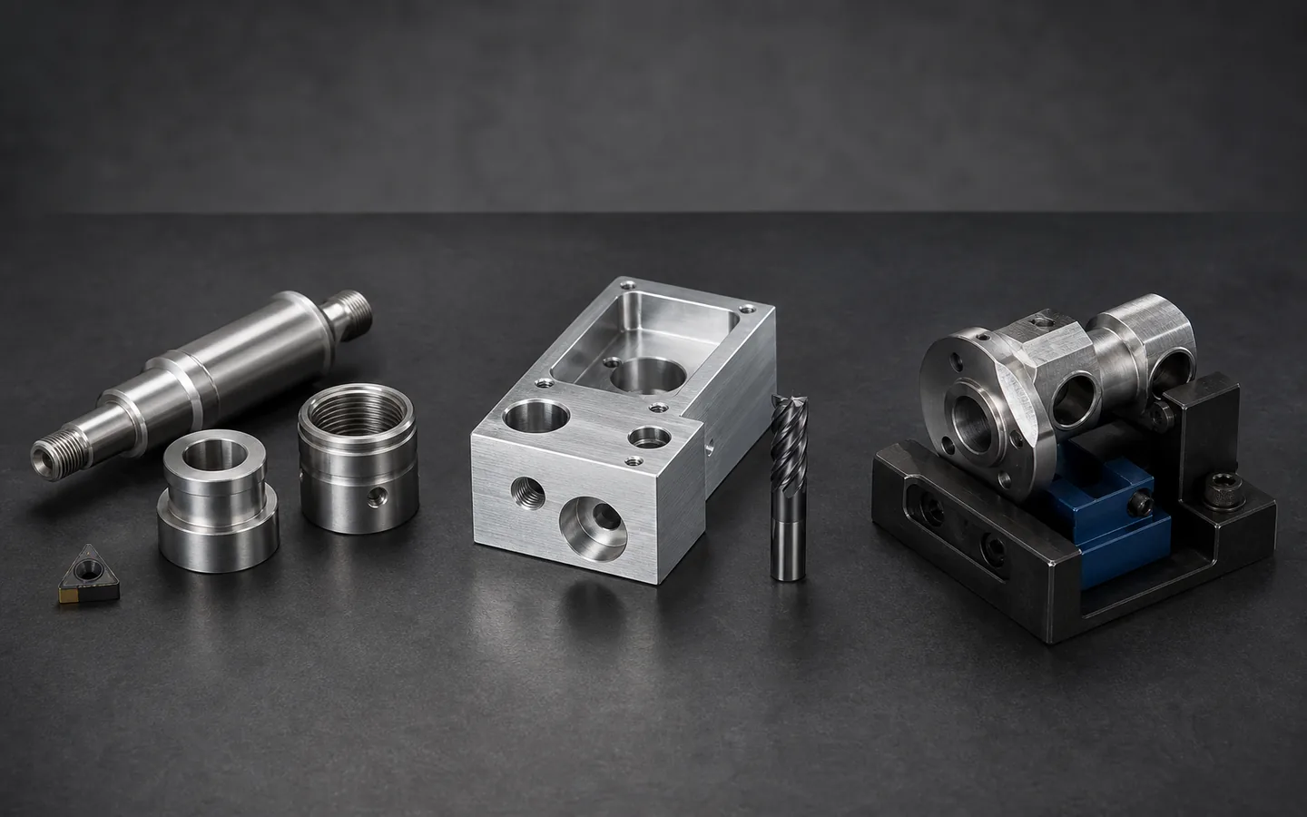
Choosing CNC milling vs turning is a geometry decision, not a brand preference. Turning fits when diameters, bores, faces and threads share a practical centerline; milling fits when planes, pockets, slots and face-oriented holes dominate. Many parts need both. State which features define function, then upload CAD so MakeNexa can compare turning-led, milling-led or mill-turn supplier routes.
Use this guide
If most controlled surfaces are concentric with one axis, start with turning. If functional relationships live on planes, pockets and multi-face hole patterns, start with milling. Mixed parts need a sequence: which setup creates the datums, and how cross holes, flats or bores transfer without losing the relationship.
Include stock form, grip or fixture strategy, quantity and inspection so the quote is not a process label contest. MakeNexa compares feasible routes across its supplier network; it does not claim milling or turning is always cheaper, faster or more accurate.
Design priorities
Start with the datum relationship that defines function, then account for off-axis features and transfer risk.
Use a rotational route when diameters, bores, faces, grooves or threads share a centerline and can be reached while the part rotates. Identify where slenderness, interrupted cuts or gripping length may affect support.
Use a prismatic route when functional relationships are based on planes, pockets, slots, face-oriented holes or multi-axis contours. Workholding must expose the features while maintaining stable reference surfaces.
Route turned features first when they establish a functional axis, then add cross holes, flats or contours with live tooling or a milling operation. Reverse the sequence when prismatic datums govern the circular feature.
Bar, tube, plate, extrusion, forging or near-net blanks change material use and holding. Quantity and revision maturity influence whether dedicated collets, soft jaws, fixtures or a combined machine are justified.
Common review gaps
The wrong first operation can make an important relationship depend on a difficult handoff between machines or setups.
A round outer profile does not automatically make a part suitable for turning if clamping is unstable, the axis is interrupted or most work is off-axis. Review how the blank can be supported throughout the operation.
Cross holes, flats, ports, bolt patterns and pockets can dominate cycle and datum strategy even on a largely turned body. Include their angular orientation and relationship to the main axis in the controlled definition.
Moving a part from a lathe to a mill or between milling orientations can break the direct relationship between features. Use functional datums, accessible locating surfaces and a coherent inspection plan for the transfer.
Turning routes need material for gripping, support and separation from stock. State which end faces, center features or witness conditions are controlled so the process plan can manage them intentionally.
Practical choices
The supplier may use one machine or several; the buyer should control the result and any route-sensitive requirement.
Establish the axis, diameters and faces in a turning setup, then create limited flats, holes or slots using live tooling or a secondary mill. This can preserve the dominant rotational logic while accommodating modest off-axis work.
Machine circular and non-circular features from plate, block or another held blank when face relationships, low aspect ratio or the lack of a stable turning grip makes a milling-led route clearer.
Use combined equipment or a deliberately controlled transfer when both geometry families are substantial. Confirm which operation establishes the datums and how cross-process relationships will be inspected.
Design decision table
Use the part's functional geometry and locating strategy instead of choosing from the process name alone. The tolerance and finish figures below are the values shops commonly publish as standard practice; the achievable result for a specific part, material and supplier is confirmed on the reviewed quote.
| Decision factor | Turning-led indication | Milling-led or mixed indication |
|---|---|---|
| Dominant geometry | Concentric diameters, bores, faces, grooves and threads | Planes, pockets, slots, hole patterns and freeform contours |
| Primary datum | A stable centerline with axial face relationships | One or more locating faces, holes or multi-axis relationships |
| Typical tolerance | ±0.125 mm (±0.005 in) as standard practice; ±0.025 mm (±0.001 in) on precision diameters, with concentricity inside 0.025 mm across features cut in one chucking | ±0.125 mm (±0.005 in) as standard practice; ±0.025 mm (±0.001 in) on precision features, with each re-fixture adding roughly 0.05 mm of positional error between faces |
| Typical surface finish | Ra 1.6 to 3.2 µm as turned; Ra 0.8 µm with a finishing pass; Ra 0.4 µm needs grinding or a hard-turn setup | Ra 1.6 to 3.2 µm as milled; Ra 0.8 µm with a finishing pass; visible tool witness on contoured faces unless a step-over is specified |
| Feature access | Features reached radially or axially during rotation | Features needing fixed orientation, multiple faces or complex tool paths |
| Starting form | Bar, tube, round blank or rotational near-net form — a 50 mm bar turned to 20 mm removes about 84% of its volume as chip | Block, plate, extrusion, casting or irregular near-net form |
| Mixed-route trigger | Substantial off-axis work after the rotational features | Critical circular feature added to a prismatic datum structure |
Turn the guide into an RFQ
Give engineering the complete geometry and functional datum story so the route can be compared without guessing from a screenshot.
Complete packages move faster: revision-matched CAD, critical dimensions, quantity and material notes are enough to open engineering review across the network.
Get a QuoteUpload the full solid model and a matched drawing rather than a partial view or diameter list
Identify the functional axis, locating faces and relationships between circular and off-axis features
Define material grade, condition, starting-form constraints and allowed stock alternatives
State quantities, repeat cadence, revision maturity and whether dedicated workholding is acceptable
Mark finish, thread, surface and edge requirements that depend on a particular operation sequence
Specify critical characteristics and evidence needed across any turning-to-milling datum transfer
Questions before routing
These answers prepare the request; the reviewed quote controls project-specific commitments.
Turning rotates the workpiece against cutting tools; milling moves rotating cutters through a held workpiece. Turning favors concentric diameters and faces; milling favors prismatic features and multi-face patterns. Both publish similar standard tolerances — commonly ±0.125 mm (±0.005 in), tightening to ±0.025 mm (±0.001 in) as precision work — but turning holds concentricity between diameters far more cheaply because they are cut in one rotation about one axis. Mixed geometry often needs both, live tooling or a controlled transfer.
Identify the datum that defines function. If a single centerline organizes most critical surfaces, turning-led is often clearer, and features cut in that one chucking can hold concentricity inside 0.025 mm at little extra cost. If planes and face relationships dominate, milling-led is often clearer. Then list off-axis features that force secondary work: each re-fixture typically adds around 0.05 mm of positional error between the two setups, so a relationship that must hold tighter than that should be cut in a single setup.
Mill-turn and live-tool routes can combine operations when geometry and quantity justify them. The advantage is not just cycle time: holding the part through one clamping avoids the roughly 0.05 mm of setup-to-setup error a transfer introduces, which is often what makes a tight off-axis position feasible at all. Feasibility, cost and inspection still depend on the submitted model, stock, tolerances and supplier equipment—not a universal process promise.
Not always. Turning a 50 mm bar down to a 20 mm shaft removes roughly 84% of the stock as chip, so on an expensive alloy the material line can outweigh the cycle-time saving against a near-net blank. Unstable grip, interrupted cuts, heavy off-axis features or poor stock utilization can erase the rotational advantage too. Compare complete cycle, setups, material and scrap risk against a milling-led alternative.
Both routes leave Ra 1.6 to 3.2 µm as standard practice, which is the normal as-machined condition. Ra 0.8 µm needs a dedicated finishing pass and slower feeds; Ra 0.4 µm or better generally implies grinding, a hard-turn setup or a polishing operation. Call out roughness only on the faces that need it — a blanket finish note applied to every surface adds cost without adding function.
Controlled CAD and drawing, critical datums, material and stock preference, features that must share an axis or face relationship, finish, quantity and inspection scope. Mark which dimensions are final after secondary ops, and flag any relationship that must hold tighter than about 0.05 mm across two faces so it can be planned as a single setup.
Next step
Apply the guide to a real drawing and RFQ package. MakeNexa routes capable suppliers from a global network covering competitor-class process categories, then returns a prepared quote or focused clarification for your revision.