 MAKENEXA
Identity and revision
Include part identity, drawing revision, units, scale where relevant, projection convention and the corresponding model revision or file reference. Make superseded versions impossible to mistake for current authority.
Engineering design resource
A feature control frame is only readable if you know which characteristic the symbol names, whether that control needs a datum, and whether the current standard still supports it. The chart below covers all 12 geometric characteristic symbols in ASME Y14.5-2018 plus the two the 2018 edition withdrew, then the checklist covers what the drawing has to carry beyond geometry. MakeNexa reviews the drawing package with the CAD before quoting.
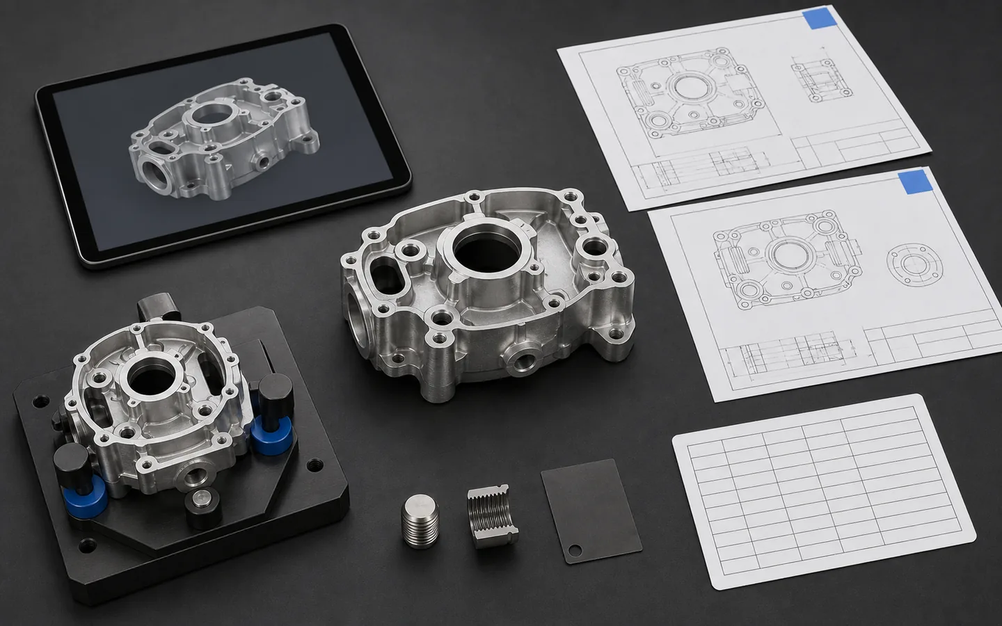
Use this guide
A manufacturing drawing should tell the recipient which part and revision it controls, which digital model belongs with it and what the model does not fully communicate. That may include datums, tolerances, threads, surface texture, material condition, finish, masking, heat treatment, inspection, documentation and notes. Repeating every nominal dimension from the model can create conflicts without adding value. Use drawing dimensions and annotations where they establish an acceptance requirement, reference or human-readable manufacturing decision.
The drawing must also agree with the RFQ and the rest of the file package. A current model paired with an obsolete drawing, inconsistent material note or different finish revision creates multiple possible purchased definitions. Resolve the conflict or identify it openly and ask for a stated interpretation. Illustrative examples can explain drawing zones, but MakeNexa does not publish customer-controlled drawings or treat an example sheet as an inspection record.
Design priorities
Organize identity, geometry, acceptance and process notes so the controlled requirement can be reviewed quickly.
Include part identity, drawing revision, units, scale where relevant, projection convention and the corresponding model revision or file reference. Make superseded versions impossible to mistake for current authority.
Define the locating scheme and the size, position, orientation, profile or runout requirements that protect function. Keep general dimensions separate from critical characteristics.
Communicate threads, inserts, edge conditions, welds, texture, sealing faces, appearance zones and other requirements that a nominal solid cannot reliably convey on its own.
State material condition, treatment, finish, masking, inspection state, sample plan and document deliverables where they control the received part or quote scope.
Where the drawing controls a weldment, bonded or fastened assembly, identify each item against a parts list, show the joints with a recognized weld or joint symbol set, and state which dimensions are controlled after assembly rather than on the loose part. Name the fastener, thread and any preload requirement instead of leaving it to be inferred from the model.
Common review gaps
Ambiguity increases when two files appear authoritative or a note names an outcome without defining its scope.
Hole count, geometry, material, revision or finish differences create competing definitions. Correct the package or state which file governs the affected requirement and request review of the discrepancy.
A general tolerance and material line may not define critical interfaces, final process state or acceptance evidence. Add feature-specific controls only where function requires them.
A thread standard, roughness value or cosmetic instruction must identify the applicable features or zones. Avoid a global note when different surfaces serve different functions.
Color, coating or treatment alone may not define preparation, protected threads, electrical contacts, fit surfaces, rack points or whether dimensions are accepted before or after finish.
Practical choices
The package can distribute information differently, but it must make the controlling source and revision explicit.
Use the model as the primary geometry source and the drawing for datums, special tolerances, notes, final condition and records. State that division clearly when both are controlled.
Use a fully dimensioned drawing where the purchasing or quality system requires it, while keeping the model synchronized and identifying any reference-only geometry.
When product definition lives in an annotated model, provide a stable human-readable export or specification that preserves revision, acceptance and document context for the selected route.
Design decision table
Use the drawing for information that must survive file exchange, quoting, manufacturing and receiving. The standards and block-tolerance figures below are the references drawings commonly cite; the controls that apply to a specific part are a buyer decision confirmed on the reviewed quote.
| Drawing zone | What it should define | Review question |
|---|---|---|
| Title and identity | Part number, revision, units, projection, model relationship and page control. ASME Y14.100 is the usual reference for drawing practice, and ASME Y14.41 where a model carries the definition. | Can the recipient identify one current purchased definition? |
| Block tolerances | Default tolerances by decimal place — commonly ±0.25 mm on one place, ±0.13 mm on two and ±0.05 mm on three, or the inch equivalents | Does the default leave only the genuinely critical features to be called out individually? |
| Geometry and datums | Controlled views, datum scheme, critical sizes and geometric relationships, with the geometric tolerancing standard named — commonly ASME Y14.5 | Do the controls follow the functional locating condition? |
| Features and surfaces | Threads, inserts, edges, roughness, welds, seals and appearance zones. Thread callouts carry pitch and class, such as M6×1.0 or a form referenced to ASME B1.1; roughness is called as Ra with a number, such as Ra 1.6 µm. | Is the scope of every local note unmistakable? |
| Material and finish | Grade or performance need, condition, treatment, coating, color and masking, with the material specification named where a certificate is expected — for example ASTM B221 or ASTM A276 | Is the final acceptance state and sequence defined? |
| Inspection and records | Critical characteristics, sampling, gauge or report need and document delivery, with surface texture referenced to ASME B46.1 where the measurement method matters | Does the evidence request match the controlled feature and project stage? |
Feature control frame
ASME Y14.5-2009 carried 14 geometric characteristic symbols. The 2018 edition withdrew two of them and carries 12: four form, two profile, three orientation, one location and two runout. Both withdrawn symbols are listed below rather than dropped, because ISO 1101 still carries them, drawings in circulation still use them, and the replacement matters more than the removal. Form controls never reference a datum; orientation, location and runout always reference at least one. Six of these characteristics have a Unicode codepoint assigned to them by name; the rest borrow a technical glyph.
| Symbol | What it controls | Category | Datum | Status in ASME Y14.5-2018 | Status in ISO 1101 |
|---|---|---|---|---|---|
| ⏤ Straightness | How far a line element or an axis may depart from a straight line | Form | No | In use | In use |
| ⏥ Flatness | How far a surface may depart from a single plane | Form | No | In use | In use |
| ○ Circularity | How far one cross-section may depart from a perfect circle | Form | No | In use | In use |
| ⌭ Cylindricity | How far a whole cylindrical surface may depart from a perfect cylinder | Form | No | In use | In use |
| ⌒ Profile of a line | Deviation of a cross-sectional outline from its true profile | Profile | Conditional | In use | In use |
| ⌓ Profile of a surface | Deviation of a whole surface from its true profile | Profile | Conditional | In use | In use |
| ∠ Angularity | Orientation of a feature at a specified angle to a datum | Orientation | Yes | In use | In use |
| ⟂ Perpendicularity | Orientation of a feature at 90 degrees to a datum | Orientation | Yes | In use | In use |
| ∥ Parallelism | Orientation of a feature parallel to a datum | Orientation | Yes | In use | In use |
| ⌖ Position | Location of an axis, centre plane or centre point against basic dimensions and datums | Location | Yes | In use | In use |
| ↗ Circular runout | Variation of one rotating cross-section relative to a datum axis | Runout | Yes | In use | In use |
| ⌰ Total runout | Variation of a whole rotating surface relative to a datum axis | Runout | Yes | In use | In use |
| ◎ Concentricity | Opposing median points of a feature relative to a datum axis | Location | Yes | Withdrawn in 2018 - use position for axis-to-axis location, or runout on a rotating feature | In use |
| ⌯ Symmetry | Opposing median points of a feature relative to a datum centre plane | Location | Yes | Withdrawn in 2018 - use position applied to the centre plane | In use |
Concentricity and symmetry were withdrawn from ASME Y14.5 because they controlled opposing median points rather than an axis or centre plane. That is rarely the functional requirement, it is routinely confused with what position already controls, and verifying it takes extensive CMM work. Both remain active in ISO 1101, so a drawing produced to ISO can legitimately carry either one and is not out of date. If either appears on a drawing you are quoting, check which standard the drawing cites before assuming a replacement, then ask what the feature actually has to do.
Turn the guide into an RFQ
Open the drawing beside the matching model and RFQ, then verify the package tells one consistent story.
Complete packages move faster: revision-matched CAD, critical dimensions, quantity and material notes are enough to open engineering review across the network.
Get a QuotePart number, drawing revision, units and corresponding model revision are current and consistent
Model-versus-drawing authority is explicit, with no unresolved geometry, quantity or material conflict
Datums and critical dimensions reflect functional interfaces rather than drafting convenience
Threads, edges, roughness, welds, sealing faces and cosmetic zones identify their exact scope
Material condition, treatment, finish, masking and final-dimensional state are defined
Inspection, sampling, first-article, material and other document requirements match the purchased scope
Questions before routing
These answers prepare the request; the reviewed quote controls project-specific commitments.
A manufacturing drawing is quotable when it fixes material and supply condition, revision and units, datums, the tolerances that carry function, thread and hole callouts, finish and masking, and the inspection evidence expected at delivery. Block tolerances carry the routine dimensions — commonly ±0.25 mm on one decimal place and ±0.05 mm on three — so only genuinely critical features need individual callouts. The supplier network routes precision-class work to ±0.025 mm and ground features to ±0.005 mm; whether a specific feature holds that in your material and geometry is confirmed in the reviewed quote.
Not every early quote requires a fully dimensioned drawing, but the package still needs to communicate tolerances, datums, threads, material condition, finish, inspection and other acceptance requirements. A model carries geometry, not acceptance: nothing in a solid body states that a bore is ±0.025 mm while the outline is ±0.25 mm, or that one face needs Ra 1.6 µm. A drawing is often the clearest controlled place for those items, and ASME Y14.41 covers the case where the model itself is meant to carry them.
Most drawings set defaults by decimal place — commonly ±0.25 mm on one place, ±0.13 mm on two and ±0.05 mm on three, with the inch equivalents where the drawing is in inches. The point of the block is to leave only the genuinely critical features to be called out individually. Setting the default to ±0.05 mm across the whole part prices every dimension as precision work. Do not cite a general tolerance standard the supplier may not hold; state the numbers on the drawing.
The buyer should state the authority rather than leave the supplier to guess. Correct the conflict where possible; otherwise identify the affected feature, name the controlling interpretation and request engineering confirmation before quoting or release.
Not necessarily. Repeating nominal geometry can create maintenance conflicts. Include the dimensions, relationships, references and notes required to define acceptance and support manufacturing or inspection under the chosen product-definition method.
Name the intended finish and material, identify applicable and masked surfaces, describe cosmetic references or acceptable variation, and state whether dimensional requirements apply before or after finishing. Roughness belongs on the drawing as a number rather than a word — Ra 1.6 µm is a requirement, "smooth" is not — and ASME B46.1 is the usual reference where the measurement method matters. Confirm exact availability per RFQ.
Identify the purchased item, the controlling specification or vendor item, allowed sources or equivalents, and which characteristics must be met versus which remain vendor-controlled. Include revision, inspection or certificate expectations, and any substitution limits so the RFQ does not treat an uncontrolled catalog item as a fully defined custom part.
Three things. An item list that ties every balloon to a part number and its revision, so the assembly and its children cannot drift apart. The joining method shown with a recognized symbol set — AWS A2.4 or ISO 2553 for welds, a named adhesive and cure condition for bonded joints, a thread and fastener callout such as M6×1.0 with any torque or preload requirement. And the dimensions that only exist once the parts are together: post-weld flatness, bore alignment and hole-to-hole spacing usually cannot be met by stacking loose-part tolerances, so control them at the assembly level rather than tightening every child part. ASME Y14.34 covers the associated lists a fabrication or assembly drawing refers to.
Settle the release state first. A sheet marked preliminary, in-work or unreleased is not a purchase definition, and a quote prepared against one expires with the next revision. A workable review confirms four things: the drawing revision matches the model revision, every general note names the features or zones it applies to, the datum scheme follows the functional interfaces rather than drafting convenience, and the inspection and document requests match the project stage. Record which revision was approved and by whom, and reissue rather than mark up a released sheet — an annotated PDF returned by email is not a controlled change, and the supplier may still be holding the superseded file.
ASME Y14.5-2009 defined 14 geometric characteristic symbols. ASME Y14.5-2018 withdrew concentricity and symmetry, leaving 12: straightness, flatness, circularity and cylindricity for form; profile of a line and profile of a surface; angularity, perpendicularity and parallelism for orientation; position for location; and circular and total runout. Many symbol charts still published online show all 14 without noting that two are no longer supported, so check which edition a chart is drawn from before relying on it.
Form controls never take a datum, because they constrain a feature against itself: straightness, flatness, circularity and cylindricity. Orientation, location and runout always take at least one datum, because they constrain a feature against something else: angularity, perpendicularity, parallelism, position, circular runout and total runout. Profile is the conditional case. Referenced to datums it controls both form and location; used without them it controls form alone.
Next step
Apply the guide to a real drawing and RFQ package. MakeNexa routes capable suppliers from a global network covering competitor-class process categories, then returns a prepared quote or focused clarification for your revision.