 MAKENEXA
Bridge production
Molded parts can support launch or supply while demand, design and a later production-tool decision become clearer.
Manufacturing service decision
Source bridge and low-volume injection molding when production-grade resin, molded geometry and repeatable parts justify tooling. MakeNexa reviews the part, resin, demand, tool strategy, gating, ejection, finish, tolerance, inspection and future production path before confirming project fit.
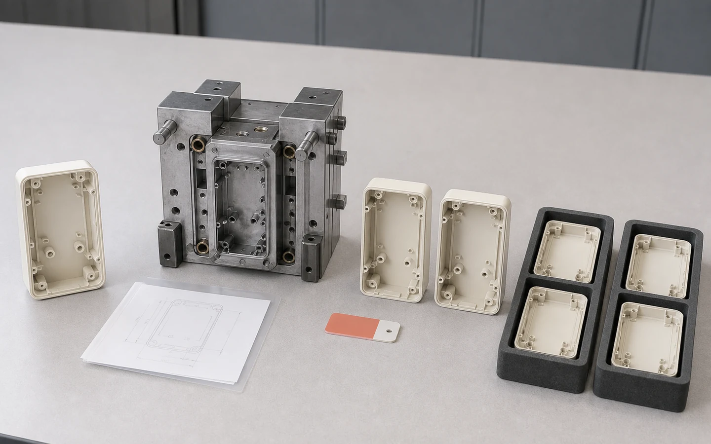
Route decision
Low-volume injection molding sits between one-off prototype routes and long-run production tooling, but there is no universal quantity where it becomes correct. Tool material, cavity strategy, part complexity, resin, finish, change risk, cycle needs and expected repeats influence the commercial break point. A small order can still require serious tooling if the geometry, material or acceptance requirements demand it.
MakeNexa reviews CNC machining, additive manufacturing, urethane casting and molding against the complete program. The RFQ should separate first-order quantity from expected lifetime demand and explain whether the goal is market validation, bridge supply, qualification or ongoing low-rate production. Tool ownership, maintenance, storage, modification, life assumptions, included samples, supplier, price and lead time must be stated in the reviewed quote.
Best-fit parts and programs
The strongest case combines production-intent material and geometry with credible repeat demand.
Molded parts can support launch or supply while demand, design and a later production-tool decision become clearer.
Production-intent resin and molded features can reveal assembly, handling and user issues that a substitute prototype may miss.
Stable periodic orders may justify a controlled tool when total demand and maintenance expectations are understood.
Living hinges, snap fits, ribs, bosses, texture and repeat cosmetic surfaces may require the intended molding process for useful evaluation.
Feasibility checks
A low initial quantity does not remove tooling, resin, qualification or change-control decisions.
Tool changes can be limited or expensive; identify unresolved interfaces, tests and expected design learning before release.
State tool material, cavities, inserts, ownership, storage, maintenance, transfer and end-of-life expectations contractually.
Exact grade, additives, color matching, drying, records and minimum purchasing quantities can affect both tooling trials and repeats.
Define sample rounds, critical dimensions, visual standard, tests and approval evidence without creating an artificial editorial gate.
Route options
The route should match material fidelity, quantity, geometry, schedule and the cost of design change.
A project-specific tool strategy may reduce initial investment while retaining the molded material and process.
Considered when change flexibility and small quantities matter more than exact injection-molded behavior.
Compared when stock material, controlled interfaces and no-tool flexibility outweigh molded geometry or per-part economics.
Decision comparison
Typical published practice for low-volume injection moulding with prototype and bridge tooling. Achievable tool life, tolerance and lead time depend on resin, geometry and tool construction, and the project requirement is confirmed on the reviewed quote rather than from this table.
| Decision area | Typical published value | Review focus |
|---|---|---|
| Typical quantity band | Roughly 100 to 10,000 parts, where tooling cost is repaid but a hardened production tool is not justified | Quantity and expected repeat, stated up front |
| Aluminium tool life | Commonly 10,000 shots and beyond depending on resin and geometry; glass-filled resins wear tooling far faster | Whether the tool covers the programme or is a bridge |
| Tooling lead time | Commonly 2 to 4 weeks to first samples for a single-cavity aluminium tool | Where tooling sits in the schedule |
| Wall thickness | 1.0 mm to 3.0 mm uniform; variation beyond about 25% of nominal causes sink and warp | Uniform wall is the single most important moulding design rule |
| Draft angle | 1° to 2° minimum on unfilled resins, and 3° and above on textured surfaces | Zero-draft walls drag on ejection and mark |
| Rib thickness | 50 to 60% of the adjoining wall; thicker ribs sink visibly on the opposite face | Stiffness added by ribs rather than by wall thickness |
| Shrinkage by resin | About 0.5% for ABS, 0.6% for polycarbonate, 1.5% for nylon and 2.5% for acetal | The tool is cut for one resin — a resin change is a tool change |
| Achievable tolerance | Commonly ±0.1 mm on small features in a stable resin, widening with wall thickness and shrinkage | Which dimensions are critical, stated with the resin |
| Cavity count | Single cavity is normal at this volume; multi-cavity belongs to production tooling | Cycle time against tool cost |
| Tool modification | Steel-safe changes — removing tool material to add part material — are straightforward; the reverse means welding or an insert | Design the first tool so likely changes are steel-safe |
| Surface finish | Standard tool finishes range from machined through polished to textured, each a separate specification | The finish grade named rather than described |
| Gate and ejector marks | Every moulded part carries a gate vestige and ejector pin witness somewhere | Where they are permitted to land |
| Melt temperature by resin | Commonly 250 °C for ABS and up to 320 °C for polycarbonate; the tool and any insert must tolerate it | Whether metal inserts or hardware go in the tool |
| Mould temperature | Commonly 40 °C to 80 °C circulating water, and it directly affects surface finish and shrinkage | Whether the tool has effective cooling designed in |
| Steel tool alternative | Pre-hardened P20 at about 30 HRC where an abrasive filled resin would wear aluminium quickly | The resin fixed before the tool material is chosen |
| Tighter feature tolerance | ±0.05 mm is achievable on small, thick-wall-free features in a stable resin, with added tool work and inspection | Which few dimensions justify it |
| Typical nominal wall | 2 mm is the usual starting point for a housing; cooling time scales with the square of the thickest section | Wall thickness as the main lever on cycle cost |
Quote inputs
Submit part requirements and the expected program, not only the first purchase quantity.
Complete packages move faster: revision-matched CAD, critical dimensions, quantity and material notes are enough to open engineering review across the network.
Get a Quote3D model and drawing with critical, cosmetic and assembly requirements
Exact resin, additives, color, records and permitted alternatives
First order, repeat batches, annual context and lifetime demand range
Draft, texture, undercuts, inserts, gates and ejector restrictions
Tool ownership, sample, change, storage, maintenance and transfer needs
Inspection, testing, packaging, labeling and delivery expectations
Questions before routing
These answers prepare the request; the reviewed quote controls project-specific commitments.
Roughly 100 to 10,000 parts — the band where tooling cost is repaid against machining or printing, but a hardened multi-cavity production tool is not justified. Below about 100, machining or urethane casting usually wins. Above 10,000, a P20 or H13 production tool with multiple cavities changes the per-part economics substantially. State the quantity and whether repeat releases are expected.
That is a commercial question that needs stating rather than assuming. Ownership, storage, maintenance, the right to move the tool to another supplier, and what happens to it at end of programme are all separate from its cost. Aluminium tooling commonly runs 10,000 shots and beyond, so a tool may outlive the relationship that created it. State the expectation in the RFQ.
In one direction easily. Removing tool material to add part material — opening a pocket, deepening a rib — is straightforward. Adding tool material to remove part material means welding or fitting an insert, which is slower, more expensive and sometimes visible on the part. This is why the first tool should be cut steel-safe wherever a dimension is uncertain: leave material on the part so the tool can be opened up later.
If the test depends on material properties, yes. A moulded ABS part publishes about 40 to 45 MPa tensile isotropically; a printed one gives 30 to 40 MPa in plane and only 30 to 70% of that across layers, with different surface, porosity and creep behaviour. Living hinges and fatigue-loaded snaps only work moulded. If the test is fit and form, printing is faster and far cheaper — tooling alone commonly takes 2 to 4 weeks.
Almost always wall thickness variation. Thick sections cool and shrink last, pulling the surface in — the visible result appears opposite a rib, a boss or a thick junction. The design rules are a uniform wall of 1.0 mm to 3.0 mm with variation held under about 25% of nominal, ribs at 50 to 60% of the adjoining wall, and generous radii at junctions. Shrinkage magnitude also depends on resin: about 0.5% for ABS against 2.5% for acetal.
Next step
Send geometry and process requirements for review. MakeNexa routes capable suppliers from a global network covering competitor-class process categories, then returns a prepared quote or focused clarification for your revision.