 MAKENEXA
Grip and ergonomics
A compliant outer region can change touch, friction and comfort when thickness, texture, hardness and use environment are defined.
Manufacturing service decision
Source overmolded grips, seals, protective surfaces, cable interfaces and multi-material housings through MakeNexa. Engineering reviews the substrate, second-shot material, bond mechanism, shutoffs, handling, tooling, appearance, quantity and functional tests before the reviewed quote is prepared.
Route decision
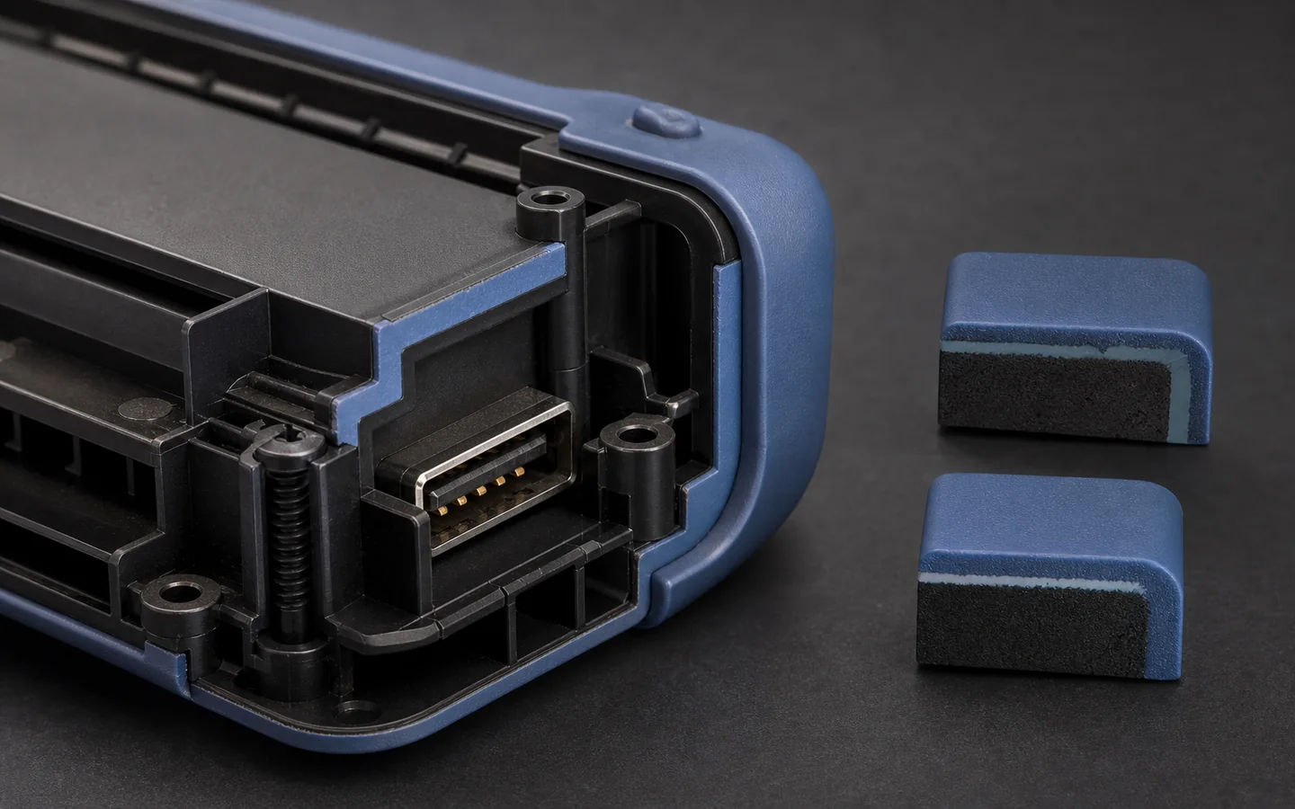
Overmolding can integrate grip, sealing, cushioning, insulation or protection onto a rigid substrate, but the second material does not automatically bond because it is soft or visually compatible. Chemical adhesion depends on the exact material pair and process window. Mechanical locks, holes, undercuts, wraparound geometry and surface preparation may be needed when adhesion is uncertain or the consequence of separation is high.
The substrate may be a molded component, machined insert, metal part, cable assembly or another controlled item. MakeNexa reviews how it is located, heated, supported and protected during the second operation; where flash, witness lines and gates are allowed; and how bond, seal and appearance will be accepted. Material pair, tooling, supplier, process, price, lead time and validation scope are confirmed only in the reviewed RFQ.
Best-fit parts and programs
Use the added material to solve a defined interface or handling problem rather than treating it as decoration.
A compliant outer region can change touch, friction and comfort when thickness, texture, hardness and use environment are defined.
Overmolded lips, boots and cable entries may reduce part count when compression, bond and leak-test requirements are clear.
Localized compliant material can cushion contact or isolate components when loads, frequency and aging conditions are understood.
Contrasting materials can mark controls or protect selected surfaces, subject to pigment, boundary and cosmetic review.
Feasibility checks
The substrate, second material and tool must be reviewed as one system.
Specify exact substrate and overmold grades; generic resin families do not establish chemical adhesion or service durability.
Through-holes, grooves, undercuts and wraparound features can provide backup retention when flow and demolding remain practical.
Parting boundaries, thin feather edges and substrate variation affect flash, witness lines and protection of functional surfaces.
Orientation, cleanliness, preheating, fixturing and damage prevention influence loading, cycle, bond and appearance.
Route options
The best solution may integrate materials in the mold or join separately produced components.
Considered when volume, material pair, boundary control and automation justify dedicated multi-material tooling.
A preformed substrate can be placed into a second tool when location, protection and handling are controlled.
Compared when service replacement, material incompatibility, change flexibility or lower tooling complexity is more valuable.
Decision comparison
Typical published practice for overmoulding elastomers and rigid resins onto substrates. Achievable bond, hardness and geometry depend on the specific material pair and tooling, and the project requirement is confirmed on the reviewed quote rather than from this table.
| Decision area | Typical published value | Review focus |
|---|---|---|
| Bonding basis | Chemical compatibility between the specific TPE grade and the specific substrate resin — not between material families | The exact grade pair, named, not TPE over ABS |
| Mechanical interlock | Through-holes, undercuts and dovetails retain the overmould where chemical bonding is weak or absent | Designed in from the start rather than added after a failed bond |
| Elastomer hardness | TPE grades run from about 30 Shore A for soft grips to 90 Shore A and into the Shore D range for structural overmoulds | The hardness stated as a number with a tolerance, not as soft or firm |
| Overmould wall | 1.5 mm to 3.0 mm typical; below about 1.0 mm the material struggles to fill and knits poorly | Whether the grip geometry is mouldable |
| Substrate wall | At least equal to the overmould wall, so the substrate does not distort under injection pressure and heat | Substrate design reviewed against the overmould, not separately |
| Melt temperature | TPE melt commonly 180 °C to 250 °C, which the substrate has to survive without softening at the interface | Whether the substrate resin's heat-deflection figure clears it |
| Substrate heat-deflection | ABS at about 98 °C at 0.45 MPa and polycarbonate at 130 °C to 140 °C at 1.8 MPa behave very differently under an overmould | The pairing reviewed thermally as well as chemically |
| Bond testing | Peel and pull tests to a stated force with a defined geometry, rather than a subjective assessment | The acceptance test named and its criteria stated |
| Two-shot against insert moulding | Two-shot moulds both materials in one machine cycle at high tool cost; insert moulding loads a moulded substrate into a second tool | Volume decides which is economic |
| Metal substrates | Metal inserts need mechanical retention and preheating — commonly 100 °C to 150 °C — because no chemical bond forms | Retention geometry and preheat stated |
| Shrinkage difference | The two materials shrink at different rates, which loads the interface as the part cools | Why a large flat overmould is harder than a small grip |
| Sequence | The substrate is fully moulded, cooled and often surface-prepared before the overmould | Whether substrate handling and cleanliness are in scope |
Quote inputs
Keep substrate and overmold definitions under one controlled assembly revision.
Complete packages move faster: revision-matched CAD, critical dimensions, quantity and material notes are enough to open engineering review across the network.
Get a QuoteAssembly model plus drawings for substrate and final overmolded part
Exact material grades, hardness, color and permitted alternatives
Bond zones, mechanical locks, shutoffs, gates and cosmetic boundaries
Substrate source, supplied condition, cleanliness and handling needs
Quantity, tool ownership, sample rounds and repeat-demand context
Bond, seal, visual, dimensional, aging and packaging requirements
Questions before routing
These answers prepare the request; the reviewed quote controls project-specific commitments.
No — bonding is specific to the grade pair, not to the material families. A TPE formulated to bond to polypropylene will not bond to polycarbonate, and two TPEs with the same Shore hardness can behave completely differently on the same substrate. Material suppliers publish compatibility data for their specific grades. Name both exact grades in the RFQ, and where bonding is uncertain or weak, design mechanical interlock — through-holes, undercuts, dovetails — from the start.
Yes, but the retention is entirely mechanical — no chemical bond forms between a thermoplastic and a metal insert. That means knurls, grooves, holes or undercuts have to be designed into the insert. Preheating the insert, commonly to 100 °C to 150 °C, narrows the thermal gradient against a melt at 180 °C to 250 °C and reduces the shrink stress that cracks the surrounding material. State the insert drawing, its tolerances and the retention features.
By a stated test with a defined geometry and a numeric acceptance criterion — typically peel or pull to a stated force — rather than by pulling at a sample by hand. Because the bond depends on the specific grade pair, the substrate's surface condition and cleanliness, and the process temperatures, it also needs testing on production-representative parts rather than on a plaque. Name the test, the sample scope and the acceptance criteria.
It removes an assembly step and replaces it with tooling complexity and a bond that has to be verified. Two-shot moulding runs both materials in one machine cycle at high tool cost; insert moulding loads a moulded substrate into a second tool, which is cheaper to tool and slower to run. Both need substrate handling, cleanliness control and bond testing. At low volume, a separately moulded part and a mechanical assembly is often cheaper.
Usually shrinkage mismatch or a thin overmould wall. The two materials contract at different rates as the part cools, and that difference loads the interface — most at the perimeter of a large flat overmould, least on a small wrapped grip. An overmould wall below about 1.0 mm also fills and knits poorly, leaving a weak edge. The fixes are mechanical interlock at the perimeter, a wall of 1.5 mm to 3.0 mm, and a grade pair with published compatibility.
Next step
Send geometry and process requirements for review. MakeNexa routes capable suppliers from a global network covering competitor-class process categories, then returns a prepared quote or focused clarification for your revision.