 MAKENEXA
Low-friction interfaces
Define mating materials, load, speed, temperature, lubrication, wear and allowed movement. A general low-friction description does not establish life or fit for the actual assembly.
Material selection decision
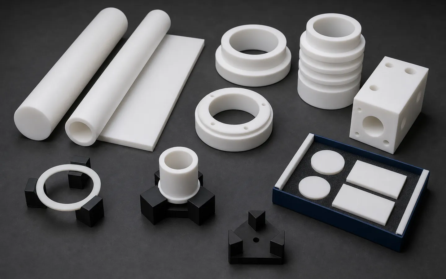
PTFE can support low-friction, chemical, electrical and temperature-related design intents, but its deformation, creep, thermal expansion and surface behavior make final dimensions and assembly context essential. MakeNexa reviews exact grade, filler, stock and supplier route; sealing, compatibility, purity, compliance and performance remain project-specific.
Selection criteria
Define the environment, load, temperature, duration, pressure, mating geometry, movement, electrical need and cleaning exposure. Separate the role of the material from the shape of the part: a ring can be a spacer, insulator, bearing or seal, and each job creates different fit and deformation questions. Name virgin or filled PTFE grade when fixed, including filler and color, or provide the properties and restrictions that control a reviewed selection.
State the measurement temperature, conditioning time, fixture or free-state condition and assembly fit for critical dimensions. Soft stock, thin walls, grooves, threads and interrupted features can deform under clamping and inspection. Define edge, burr, surface, cleanliness and packaging without assuming that a smooth white part is clean or suitable for a regulated environment. MakeNexa returns a quote-specific route rather than a universal sealing or chemical-compatibility claim.
Where the material fits
Material advantages only become useful when load, time, temperature and accepted state are visible.
Define mating materials, load, speed, temperature, lubrication, wear and allowed movement. A general low-friction description does not establish life or fit for the actual assembly.
Provide exact media, concentration, temperature, exposure, voltage or cleanliness requirement and select the exact grade using approved data. Fillers and processing may change the relevant behavior.
Rod, tube, sheet or billet can be machined into rings, bushings, insulators and complex bodies. Workholding, sharp tools, wall support, burr control and relaxation affect the final dimensional plan.
State final free-state dimensions, mating geometry, compression, surface and particulate or cleaning needs. Package soft parts so edges and sealing-like surfaces are not distorted or contaminated.
Material tradeoffs
A dimension observed immediately after machining or under fixture load may not represent the service state.
Sustained load and temperature can change compression and fit. Provide assembly force, duration, support and service conditions, then validate the complete joint where performance matters.
Soft rings and thin walls may change under calipers, fixtures and gauges. Define a low-force method, support, conditioning and free-state or restrained state for critical characteristics.
Glass, carbon, bronze and other fillers can change mechanical, wear, electrical, color, machining and cleanliness behavior. State the exact grade and ensure material records match the released part.
Color and surface do not prove particulate, residue, bioburden or regulated cleanliness. Specify cleaning, handling, packaging and evidence appropriate to the real environment.
Grade and route choices
The selected route should state what material behavior it addresses and what still requires application validation.
Use an exact virgin grade when its chemical, electrical, friction or purity context fits. Control stock, dimensional state, deformation, surface, cleaning and material evidence for the part.
Use a named filled compound when wear, deformation or another property drives selection. Review filler compatibility, machining, contamination, color and required documentation rather than substituting generically.
PEEK, acetal, UHMW or another polymer may offer different stiffness, temperature, machining or wear behavior. Compare exact service requirements and revalidate the assembly before changing material.
Material comparison
Typical published values for virgin unfilled PTFE. Filled grades differ substantially, and actual values vary with grade, stock form and processing history, so the project requirement is confirmed on the reviewed quote rather than from this table.
| Property or decision factor | Typical published value | Routing consequence |
|---|---|---|
| Coefficient of friction | About 0.04 to 0.10 — the lowest of any solid material | The whole reason to specify it, against 0.2 to 0.35 for acetal |
| Tensile strength | About 20 to 35 MPa, against 70 MPa for acetal | It is a low-friction material, not a structural one |
| Tensile modulus | About 0.5 GPa, roughly a sixth of acetal at 3.1 GPa | Very soft: it deforms under clamping load and under its own fixturing |
| Creep under load | PTFE cold-flows under sustained stress at room temperature — a clamped part keeps deforming for the life of the joint | The single most common design failure; filled grades reduce it, they do not remove it |
| Continuous service temperature | Commonly quoted around 260 °C, with melting near 327 °C | The widest service range of the common machinable polymers |
| Chemical resistance | Inert to almost every industrial chemical | Attacked by very few reagents — usually the reason it was specified |
| Thermal expansion | About 100 to 160 µm per metre per °C, roughly ten times steel and well above acetal at 110 | A 100 mm feature moves 0.10 to 0.16 mm across a 10 °C swing |
| Water absorption | Below 0.01% | Dimensionally unaffected by humidity, unlike nylon |
| Density | About 2.15 to 2.20 g/cm³ — the heaviest of the common machinable plastics, against acetal at 1.41 and nylon at 1.14 | Part mass, and stock cost per part on a large section |
| Processing route | Not injection mouldable: PTFE is compression moulded or ram extruded into stock and then machined | Quantity does not unlock a moulding route the way it does for other polymers |
| Filled grades | Glass, carbon, bronze and graphite fills raise stiffness and cut creep, at the cost of some chemical resistance and a higher friction coefficient | State the load and the chemistry so the fill can be reviewed |
| Bonding | PTFE's surface energy is so low that nothing adheres without chemical etching | Mechanical retention, or a specified surface treatment |
| Machined tolerance | ±0.1 mm is realistic; tighter fits are undermined by the low modulus and high thermal expansion rather than by the machine | State the measurement temperature and the free-state condition |
Material RFQ inputs
Define the service and measurement state so material and dimensional acceptance are not guessed.
Complete packages move faster: revision-matched CAD, critical dimensions, quantity and material notes are enough to open engineering review across the network.
Get a QuoteSubmit the controlled model, drawing, revision and complete service environment
State virgin or filled PTFE grade, filler, color, stock form and material evidence
Define media, temperature, load, duration, movement, electrical and cleanliness requirements
Mark thin walls, rings, grooves, threads, fits, sealing-like and burr-sensitive surfaces
Specify conditioning, measurement temperature, inspection force and free or restrained state
List quantities, cleaning, handling, packaging, tests, documents and permitted alternatives
Questions before routing
These answers prepare the request; the reviewed quote controls project-specific commitments.
Not in the way most engineering plastics are. It ignores humidity — water absorption is below 0.01% — but it moves 100 to 160 µm per metre per °C with temperature, roughly ten times steel, and at about 0.5 GPa modulus it deforms under clamping load. Worse, it cold-flows: under sustained stress at room temperature a PTFE part keeps deforming for the life of the joint. Measure in the free state at a stated temperature, and design so no feature relies on PTFE holding a dimension under load.
Virgin PTFE has the best chemical resistance and lowest friction at about 0.04 to 0.10, but it is the worst for creep and wear. Glass, carbon, bronze and graphite fills raise stiffness, cut cold flow substantially and improve wear life, at the cost of some chemical resistance and a slightly higher friction coefficient. If the part is loaded or sliding under load, filled is usually right; if it is a chemically exposed seal or liner at low load, virgin is. State the load, the counterface and the chemistry.
Yes, and it is one of the easier materials to cut — but holding a dimension is the hard part. At about 0.5 GPa modulus it deflects under cutting and clamping forces, and its thermal expansion of 100 to 160 µm per metre per °C means the part measured warm off the machine is not the part measured cold. ±0.1 mm is realistic; tighter fits need free-state measurement at a stated temperature and careful workholding. PTFE is machined from compression-moulded or ram-extruded stock, since it cannot be injection moulded.
No, and creep is why. A PTFE seal that is torqued into place keeps cold-flowing under that sustained load and loses its sealing force over time — this is the most common PTFE failure in the field. Spring-energised designs, filled grades and controlled compression exist to manage it. State the pressure, temperature, fluid, cycle count, compression and expected service life so the geometry and the grade can be reviewed together, rather than specifying PTFE and assuming it seals.
Next step
Send the material requirement with geometry and use context. MakeNexa routes capable suppliers from a global network covering competitor-class process categories, then returns a prepared quote or focused clarification for your revision.