 MAKENEXA
FDM and extrusion printing
Fast concept models, fixtures and larger thermoplastic parts.
Review layer direction, wall thickness, support access, heat and appearance needs.Industrial 3D printing
Upload the model and say what the part must do—fit check, functional test, fixture or end-use. MakeNexa compares polymer, resin and metal additive routes on geometry, material behavior, orientation, surface and inspection before the quote—not from a process name alone.
Start this RFQ Review the route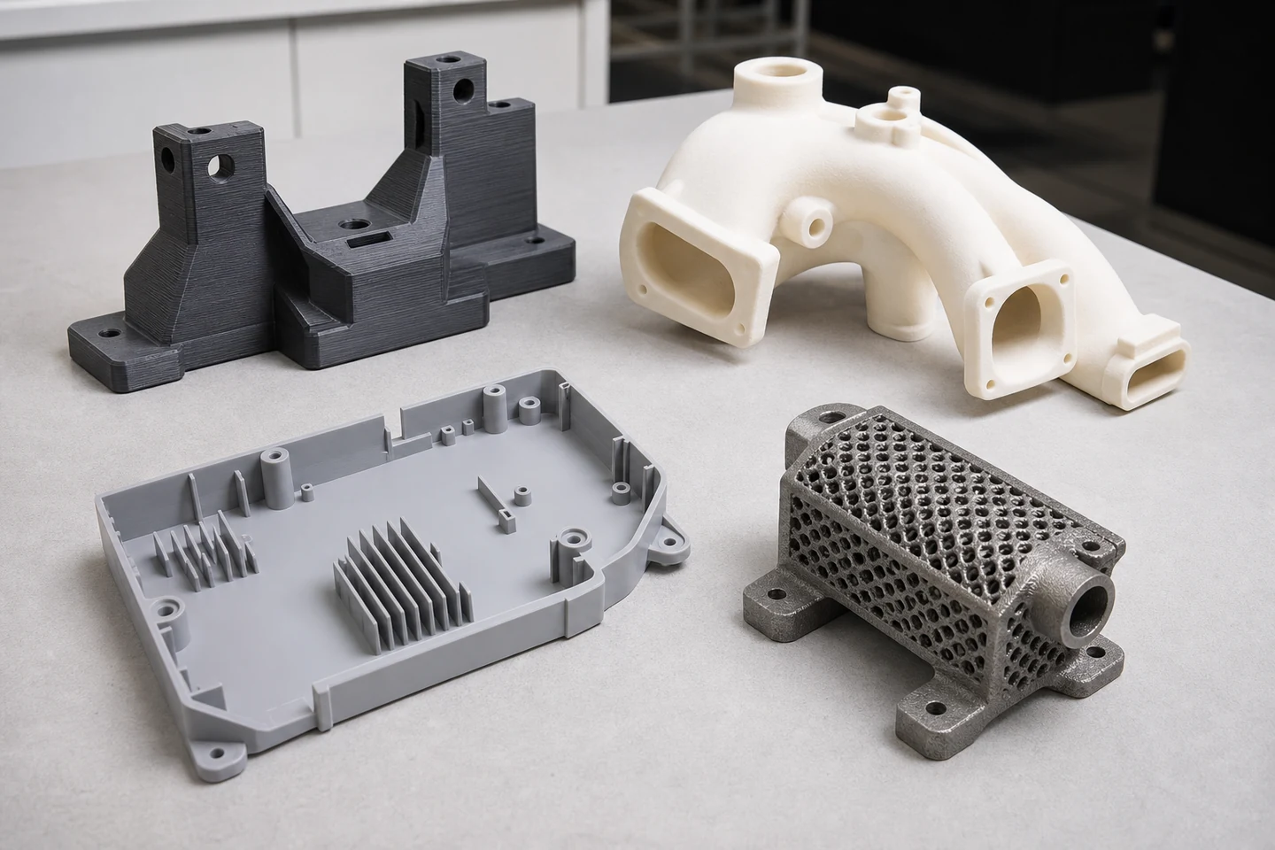
Decision guide
A visual model, a snap-fit prototype, a duct with internal channels and a load-bearing bracket do not ask the same thing from additive manufacturing. Describe temperature, load, chemical exposure, appearance, flexibility, dimensional interfaces and whether the part is a prototype or an end-use component.
Build orientation can change strength direction, support marks, surface texture and measurement results. The reviewed route therefore considers geometry and acceptance together. Exact machine, layer setting, branded material, tolerance, price and lead time remain project-specific.
Route options
MakeNexa can source the principal additive routes offered by leading manufacturing platforms. The reviewed quote confirms which specific process and supplier fit the file.
Fast concept models, fixtures and larger thermoplastic parts.
Review layer direction, wall thickness, support access, heat and appearance needs.Detailed visual models, smooth surfaces and fine features.
Review resin behavior, UV exposure, thin features, support marks and post-cure needs.Functional nylon parts, nested builds and complex geometry without conventional support structures.
Review powder escape, wall thickness, dimensional interfaces, dye or finish needs.Complex metal geometry, internal channels and consolidation opportunities.
Review alloy, support removal, machining allowance, heat treatment and inspection plan.Decision table
A quote improves when these requirements are explicit.
| Decision input | Questions to answer | Route effect |
|---|---|---|
| Function | Visual model, fit check, functional test, tool, spare or end-use part? | Sets the level of material and acceptance evidence needed |
| Process accuracy | FDM at ±0.2 mm or ±0.2%; SLA at ±0.1 mm or ±0.1%; SLS and MJF at ±0.3 mm or ±0.3%; metal powder bed at ±0.1 mm or ±0.2% | The route follows the tolerance, not the other way round |
| Directional strength | FDM interlayer strength commonly 30 to 70% of the in-plane value; MJF and SLS are closer to isotropic at about 48 MPa in PA12 | Load direction has to be stated, not just the material |
| Environment | Loads, heat, chemicals, moisture, UV or flame limits. SLA resins soften near 50 °C, PA12 melts near 178 °C, PEI holds to about 200 °C | Narrows process and material candidates |
| Geometry | Thin walls from 0.5 mm on powder bed and 1.2 mm on FDM; overhangs self-support to roughly 45°; enclosed volumes need 4 to 5 mm escape holes | Changes orientation, support, escape and cleanup strategy |
| Surface | As built: Ra 8 to 15 µm on powder bed, Ra 10 to 25 µm on FDM walls, Ra 1 to 5 µm on SLA up-faces, Ra 6 to 20 µm on metal | Nothing sealing or sliding should be left as built |
| Interfaces | Which dimensions, threads, bores or mating surfaces control function? Metal parts are machined after stress relief | May require drawing control or secondary machining |
| Sealing | Powder-bed parts are slightly porous and can leak under pressure without infiltration or coating | State pressure, fluid and the acceptance test |
Preparation
Call out these conditions so they can be reviewed with the chosen process.
Frequently asked questions
Use the submitted quote and written clarification as the project-specific record.
You may name a preferred process, but it is also acceptable to describe the use case and select Not Sure. The review compares geometry, material behavior, finish, quantity and acceptance needs.
It may be enough for a basic geometry review, but STEP or native CAD is more useful when dimensions or downstream machining matter. Add a 2D drawing for controlled tolerances and interfaces.
Many routes can support dyeing, smoothing, painting, inserts, machining or coating. Compatibility and the final acceptance method are confirmed for the material and supplier route.
No universal tolerance applies across all processes, materials, orientations and geometries. Identify critical dimensions so the reviewed quote can state the applicable approach.
Ready for review
You will receive a stable RFQ reference. MakeNexa will assess the package, request clarification when needed and return a reviewed quote or clear next action.