 MAKENEXA
Brackets and supports
Angle brackets, channels and equipment supports often combine bends with holes, slots, captive hardware and load-bearing interfaces.
Manufacturing service decision
Source brackets, panels, covers, frames and other formed components through MakeNexa's global supplier network. Engineering reviews the flat-pattern definition, material and thickness, bend geometry, feature location, finish, quantity and inspection needs before the reviewed quote is prepared.
Route decision
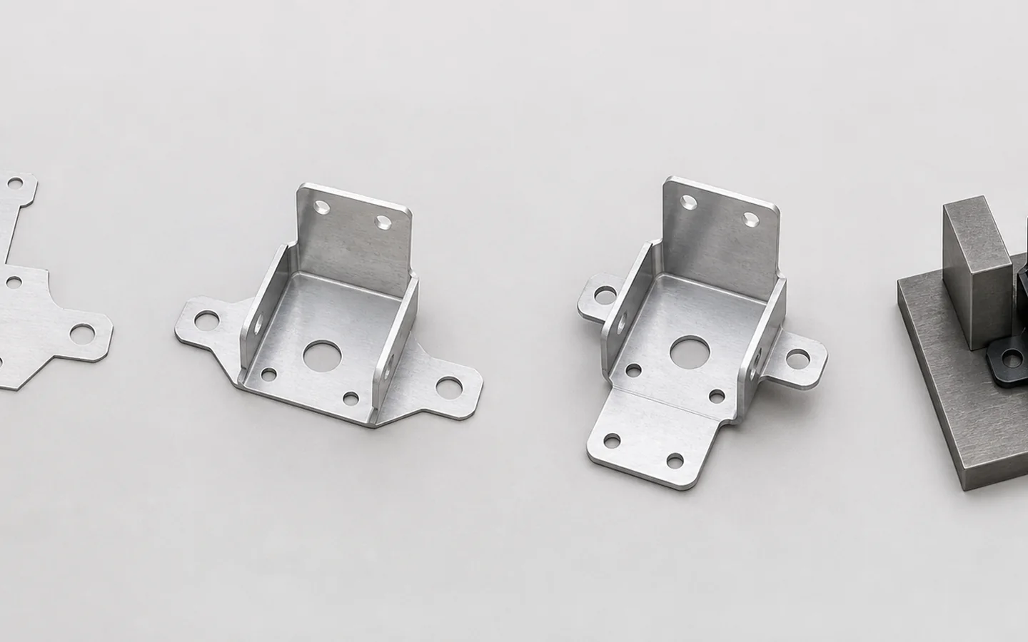
A bent sheet part is purchased in its finished three-dimensional condition, but it is manufactured through a sequence that begins with sheet stock and a flat blank. Bend radius, tooling access, bend direction, flange length, hole position and material behavior affect whether the blank can be cut and formed repeatably. A visually simple bracket can therefore need more planning than its feature count suggests.
MakeNexa reviews the native model or STEP file together with a revision-matched drawing. The review separates function-critical dimensions from reference flat-pattern information, checks features close to bends, identifies likely forming and measurement questions, and considers cutting, deburring, hardware, welding and finishing as one route. Exact tooling, bend deduction, achievable tolerances, supplier, price and timing remain specific to the reviewed RFQ.
Best-fit parts and programs
Use the finished geometry and assembly job to frame the process instead of assuming every fold follows the same rule.
Angle brackets, channels and equipment supports often combine bends with holes, slots, captive hardware and load-bearing interfaces.
Access panels, guards and covers may require controlled outer dimensions, edge safety, cosmetic faces and repeatable attachment points.
Multi-bend frames, trays and bases need bend-sequence, corner condition, flatness and assembly-clearance review.
Formed parts can support design validation and recurring production when revision, quantity and tooling assumptions are clear.
Feasibility checks
Resolve these details before a supplier has to infer design intent from a model alone.
Very small radii, short flanges or return bends may conflict with material behavior, tooling reach or practical setup.
Holes, slots, cutouts and hardware close to a bend can distort or require a different operation sequence.
Angular, flange, hole-to-bend and overall dimensions do not respond identically to material and setup variation.
Grain orientation, brushed direction, protected faces and bend marks should be stated when they affect strength or appearance.
Route options
The quote should represent the complete finished component, not an isolated press-brake step.
Laser, punch, waterjet or another cutting route is selected with edge, feature and quantity requirements in view.
PEM-style hardware, rivets, welding or assembly can be sequenced around access, heat and final dimensional needs.
Powder coat, plating, anodizing, brushing or passivation may require masking, rack-point and final-condition inspection planning.
Decision comparison
Typical published practice for press-brake forming. Achievable radii, tolerances and feature spacing depend on material, thickness, tooling and the supplier's press, and the project requirement is confirmed on the reviewed quote rather than from this table.
| Decision area | Typical published value | Why it matters |
|---|---|---|
| Minimum inside bend radius | About 1 times material thickness for 5052-H32 aluminium and mild steel; 2 to 3 times thickness for 6061-T6, which cracks at tighter radii | The alloy decides the radius before the tooling does |
| Grain direction | A bend running with the grain needs a larger radius than the same bend across it | Flat patterns should state grain direction where the bend is tight |
| Bend angle tolerance | Commonly ±1°, tightening to ±0.5° with added setup and inspection | Angular error accumulates across multiple bends |
| Dimension across a bend | Commonly ±0.25 mm on a single bend, growing with each additional bend in the chain | Which dimensions are measured from which datum face |
| Bend relief | A relief at least material thickness wide prevents tearing where a bend meets an unbent edge | Designed in rather than added by the shop |
| Hole to bend distance | At least 2.5 times material thickness plus the bend radius, or the hole deforms into an oval | The most common avoidable rework on formed parts |
| Minimum flange length | About 4 times material thickness plus the bend radius, so the flange clears the die | Shorter flanges need special tooling or a different sequence |
| K-factor | Commonly 0.33 to 0.44 depending on material and radius, and it sets the flat-pattern length | Why a flat pattern developed with the wrong assumption comes out short |
| Springback | Every material springs back; harder tempers spring back more and are compensated by overbending | Why a first article is worth more on a formed part than on a machined one |
| Tooling marks | Die contact leaves witness marks on the outside of every bend as a matter of process | Whether they are cosmetically acceptable, stated explicitly |
| Bend sequence | Later bends can become unreachable as the part closes up | Whether the geometry is formable in any order at all |
| Edge condition | Cut edges near a tight bend crack more readily; a deburred or dressed edge bends better | Whether edge preparation before forming is in scope |
| Worked example, 2 mm 5052 | Minimum inside radius about 2 mm; a hole must sit at least 7 mm from the bend line, being 2.5 times the 2 mm thickness plus the 2 mm radius | The rules become concrete once thickness is fixed |
| Worked example, 2 mm 6061-T6 | Minimum inside radius 4 mm to 6 mm — the same geometry that forms cleanly in 5052 cracks in 6061 | Alloy substitution is not free on a formed part |
| Minimum flange, 2 mm material | About 10 mm, being 4 times the 2 mm thickness plus the bend radius, so the flange clears the die | Short flanges need special tooling or a redesign |
| Bend relief width | At least material thickness — 2 mm on 2 mm stock — where a bend meets an unbent edge | Designed in, or the corner tears |
| Cut-edge tolerance before forming | Commonly ±0.13 mm on the laser-cut flat profile, before any bend error is added | Flat features hold far tighter than anything across a bend |
| Cut-edge surface | Near Ra 3.2 µm as cut, with a narrow hardened band that bends less readily than the parent metal | Whether edge dressing before forming is in scope |
Quote inputs
Keep the formed model, drawing and finish definition under one revision.
Complete packages move faster: revision-matched CAD, critical dimensions, quantity and material notes are enough to open engineering review across the network.
Get a QuoteSTEP or native formed model plus a revision-matched drawing
Material grade, temper, thickness and grain or cosmetic direction
Critical bend angles, radii, flange and overall dimensions
Hole, slot, hardware and cutout relationships to bend lines
Deburr, weld, finish, masking, color and protected-face requirements
Quantity, inspection, packaging, labeling and delivery expectations
Questions before routing
These answers prepare the request; the reviewed quote controls project-specific commitments.
Provide the 3D model as the controlling geometry and a flat pattern only as a reference, clearly marked. Flat-pattern length depends on the K-factor — commonly 0.33 to 0.44 depending on material and radius — and on the tooling the supplier actually has, so a pattern developed with different assumptions comes out the wrong length. Give the formed model, the material and thickness, the bend radii and the grain direction where a bend is tight.
Not closer than about 2.5 times material thickness plus the bend radius, or the hole deforms into an oval as the material stretches around the bend. This is the most common avoidable rework on formed parts. Where a hole genuinely has to sit close, the alternatives are to pierce it after forming as a secondary operation, or to add a relief slot. State which hole positions are functional and which are clearance.
Because 6061-T6 needs an inside bend radius of about 2 to 3 times material thickness and cracks below that, where 5052-H32 bends at roughly 1 times thickness. 6061 is a machining alloy that happens to be available as sheet; 5052 is a forming alloy. If the part is folded rather than machined, 5052 is usually the correct material — it also resists salt water better and welds without losing a heat-treated condition it never had.
No — die contact leaves witness marks on the outside of every bend as a matter of process, not as a fault. What varies is severity, and that depends on tooling, material and finish. If the outside of a bend is a cosmetic surface, say so explicitly, state the acceptance basis with a reference where appearance is contractual, and expect protective film or urethane-faced tooling to appear as a cost. Silence gets standard tooling and standard marks.
The formed 3D model as controlling geometry, plus material and temper, thickness, bend radii, and grain direction where a bend is tight — because the alloy decides feasibility before tooling does, at about 1 times thickness in 5052-H32 against 2 to 3 times in 6061-T6. Then hole-to-bend clearances at 2.5 times thickness plus the radius, flange lengths, which faces are datums, angular and across-bend tolerances at ±1° and ±0.25 mm, cosmetic surfaces, hardware and finishing. Send those and formability, tooling availability, price and lead time come back on the reviewed quote.
Next step
Send geometry and process requirements for review. MakeNexa routes capable suppliers from a global network covering competitor-class process categories, then returns a prepared quote or focused clarification for your revision.