 MAKENEXA
Large concept and fit models
Housings, ducts and equipment envelopes can be evaluated without tooling when layer texture and route-specific accuracy are acceptable.
Manufacturing service decision
For FDM thermoplastic parts—concept models, functional prototypes, jigs, fixtures or selected end-use components—send material, orientation, load direction, support, layer and surface expectations with the model. MakeNexa reviews those inputs before the reviewed quote is prepared. Price and timing stay project-specific once the package is clear.
Route decision
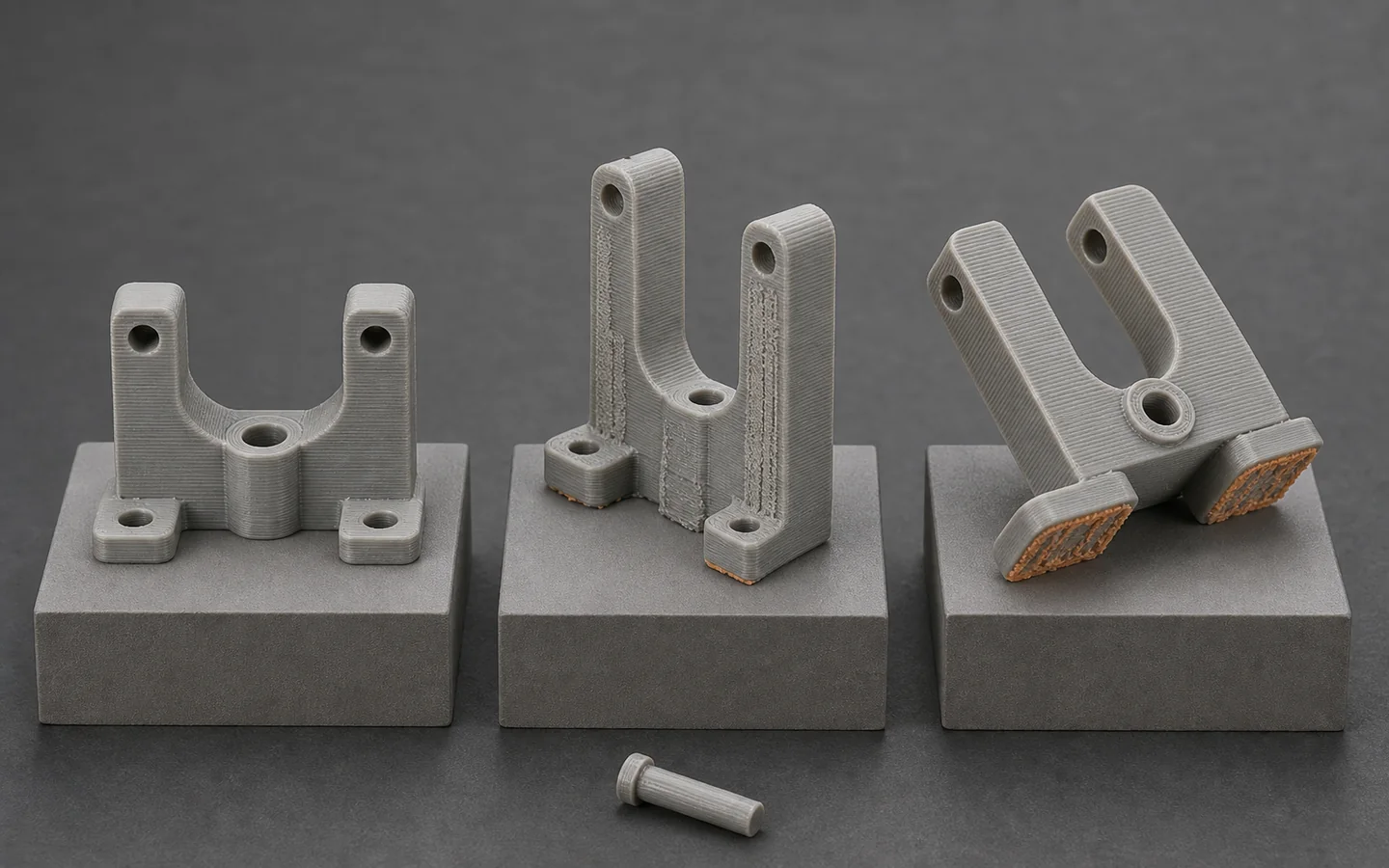
FDM can be a practical route for large prototypes, quick design iterations, fixtures and thermoplastic parts where visible layers are acceptable. Printed roads and layers make strength, sealing, surface and dimensions direction-dependent. Two parts built from the same model can behave differently if orientation, infill, shell, material condition or post-processing changes, so functional requirements should lead the RFQ.
MakeNexa reviews FDM alongside SLA, SLS, MJF, CNC machining and molding. The buyer should identify load cases, temperature and chemical exposure, critical mating features, appearance surfaces and whether the part is a demonstration model or an operational component. Exact material, build strategy, support, equipment, supplier, tolerance, price and timing are confirmed through the reviewed quote.
Best-fit parts and programs
Match the process to iteration speed, scale, material behavior and the way the part will be used.
Housings, ducts and equipment envelopes can be evaluated without tooling when layer texture and route-specific accuracy are acceptable.
Assembly aids, nests, drill guides and handling tools may benefit from fast iteration and embedded ergonomic features.
Selected materials can support mechanical or environmental trials when orientation and test conditions are defined.
Covers, adapters and replacement parts may be viable when appearance, lifetime and process consistency match the use.
Feasibility checks
Process settings should support stated requirements instead of becoming uncontrolled purchasing details.
Layer interfaces can be weaker or less sealed than in-layer paths; show loads and critical directions.
Overhang supports can leave marks or affect holes, channels and cosmetic faces after removal.
Mass, stiffness, fastening and machining behavior depend on shell, internal structure and local solid regions.
Large flat geometry, material choice, heat, moisture and annealing assumptions can affect final shape and fit.
Route options
Process selection balances size and speed with surface, detail, material and production needs.
Compared when smooth presentation surfaces, fine detail or clear-resin options outweigh thermoplastic scale and toughness.
Considered for support-free complex polymer geometry, batch density and more uniform powder-bed behavior.
Considered for stock-grade material, flatness, controlled interfaces, threads or low quantities with demanding fits.
Decision comparison
Typical published values for fused-deposition routes on a 0.4 mm nozzle. Layer height, accuracy, wall and surface all move with material, machine, orientation and the supplier's process window, so the project requirement is confirmed on the reviewed quote rather than read off this table.
| Process variable | Typical published value | What to state in the RFQ |
|---|---|---|
| Layer height | 0.2 mm for most functional parts; 0.1 mm where detail or surface matters; 0.3 mm for draft geometry. A 0.05 mm layer is possible on fine features and roughly quadruples build time against 0.2 mm. | Which surfaces need the finer layer, rather than a single layer height for the whole part |
| Dimensional accuracy | Commonly quoted as ±0.2 mm or ±0.2% of the nominal length, whichever is larger, on well-supported features | The few dimensions that are functionally critical, so they can be oriented and measured deliberately |
| Minimum wall | About 1.2 mm carries three perimeters at a 0.4 mm nozzle; 0.8 mm prints but splits along layer lines under load; 2 mm and above behaves as a structural wall | Whether a thin wall is cosmetic or load-bearing |
| Self-supporting angle | Overhangs hold to roughly 45° from vertical without support; below that the surface carries support witness marks | Faces that must stay clean, so orientation can protect them |
| As-built surface | Ra 10 to 25 µm on vertical walls at a 0.2 mm layer, with visible stair-stepping on shallow slopes | Cosmetic zones and the finish they need; smoothing, sanding or machining is a separate operation |
| Directional strength | Interlayer (Z) strength commonly reaches only 30 to 70% of the in-plane value for the same material | The load direction and magnitude, not only the resin name |
| Service temperature | Published heat-deflection figures land near 55 °C for PLA, 70 °C for PETG, 90 °C for ABS and 130 °C for polycarbonate | The service temperature the part actually sees, including transport and cleaning |
| Build envelope | Common machines build within about 300 × 300 × 300 mm; larger geometry needs a split and bonded joint or a large-format supplier route | Envelope, and whether a bonded joint is acceptable in the final part |
Quote inputs
Describe what the print must do, not only how quickly it is needed.
Complete packages move faster: revision-matched CAD, critical dimensions, quantity and material notes are enough to open engineering review across the network.
Get a Quote3D model and drawing for controlled features
Part purpose, loads, environment and expected service duration
Material or performance requirements and permitted alternatives
Orientation-sensitive features, fits, inserts, threads and support limits
Layer, surface, color, finishing and cosmetic-zone expectations
Quantity, inspection, packaging, labeling and delivery requirements
Questions before routing
These answers prepare the request; the reviewed quote controls project-specific commitments.
No. A printed part is a stack of welded layers, and the weld across layers is weaker than the material within one. Interlayer strength commonly reaches 30 to 70% of the in-plane value for the same filament, so a bracket loaded along the build direction can fail well below the datasheet number. Provide the load direction, magnitude and test condition so orientation can be chosen for the load rather than for build time.
Accuracy is commonly quoted as ±0.2 mm or ±0.2% of the nominal length, whichever is larger, on features that are well supported during the build. Tall thin geometry, large flat spans and down-facing surfaces drift further than that. Holes usually print undersize because the extrusion pulls inward on the curve, so a 6 mm hole that must take a dowel is normally printed small and reamed. Mark the few dimensions that are critical instead of applying a general tolerance to the whole model.
Sealing is not automatic — the layer interfaces leak before the material does. Walls of 2 mm or more, higher infill, a coating or an epoxy seal are the usual routes, and each is a separate operation. State the pressure, fluid, duration and acceptance test in the RFQ so the wall and the sealing method can be reviewed together.
Usually yes, with heat-set brass inserts as the common route. Plan a boss wall of at least 1.5 mm of solid material around the insert and a pilot hole matched to the insert's published dimensions. Provide insert type, installation method, load, torque, access and inspection needs so local wall and solid-region design can be reviewed with the supplier route.
0.2 mm on a 0.4 mm nozzle covers most functional work and is the usual default. Drop to 0.1 mm where surface finish or fine detail matters, or 0.05 mm on small features at roughly four times the build time. Go up to 0.3 mm where geometry is coarse and speed matters. The choice affects more than appearance: finer layers improve the as-built surface from around Ra 25 µm toward Ra 10 µm and resolve smaller features, but they do not fix interlayer strength, which stays at 30 to 70% of the in-plane value regardless. State which surfaces need the finer layer rather than applying one height to the whole part.
FDM routes commonly use thermoplastic filament families such as PLA, ABS, PETG, nylon, TPU and selected filled or higher-temperature grades. Heat resistance is usually the deciding factor: published heat-deflection figures run near 55 °C for PLA, 70 °C for PETG, 90 °C for ABS and 130 °C for polycarbonate. Exact resin, color, chemical or temperature needs, orientation and supplier stock are confirmed per RFQ. There is no single default FDM plastic for every part.
Next step
Send geometry and process requirements for review. MakeNexa routes capable suppliers from a global network covering competitor-class process categories, then returns a prepared quote or focused clarification for your revision.