 MAKENEXA
Corrosion and surface protection
An anodized layer can protect suitable aluminum parts when alloy, sealing, environment and damage expectations are defined.
Manufacturing service decision
Anodizing is an electrochemical conversion of the aluminum surface, not a coating laid on top, so it changes both appearance and dimensions. Most work is MIL-A-8625 Type II sulfuric at 5 to 25 µm or Type III hard anodic at 25 to 50 µm. Roughly half the coating grows outward, so a 20 µm Type II finish adds about 10 µm per surface and around 20 µm on a diameter — enough to matter on threads and close-fitting bores. Define type, class, colour reference, masking and whether stated dimensions are before or after coating, then upload CAD and drawings so MakeNexa can review the finish route across its supplier network.
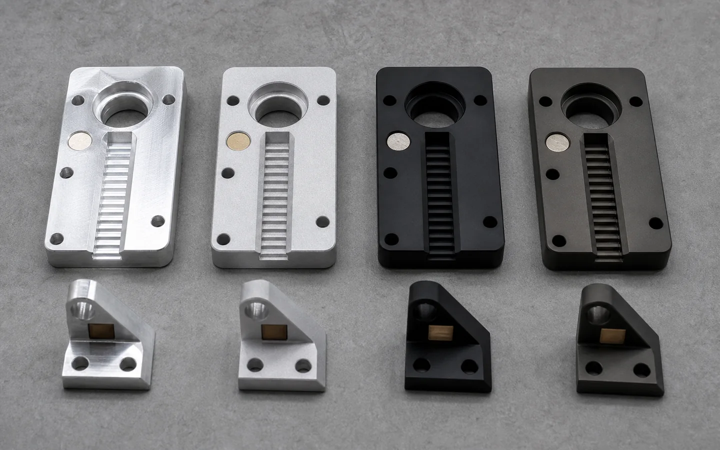
Route decision
Anodizing converts the aluminum surface rather than applying an independent paint film. It can support corrosion resistance, wear behavior, electrical insulation or appearance, depending on finish type and project requirements. Alloy composition, temper, raw surface, machining marks, welds and part geometry influence the final color and texture, so a color name alone cannot establish a consistent visual standard.
The coating affects final dimensions at bores, threads, fits, sealing faces and electrical interfaces. Rack contact, drainage, trapped chemistry and masking also need deliberate locations. MakeNexa reviews anodizing with the machining or fabrication route and inspects the part in its specified final condition. Exact process standard, thickness, color range, supplier, price, timing and inspection are confirmed per RFQ.
Best-fit parts and programs
Name the required function first so finish type and acceptance can be reviewed appropriately.
An anodized layer can protect suitable aluminum parts when alloy, sealing, environment and damage expectations are defined.
Harder anodize routes may support sliding or handling surfaces, but thickness, roughness and mating components need joint review.
Clear, black and colored finishes depend on alloy, texture, dye or process and a realistic visual comparison standard.
Insulated areas and conductive grounding contacts require controlled finish coverage and masking rather than general notes.
Feasibility checks
The finish must be planned before final dimensions and appearance are released.
Different alloys, tempers, weld filler and even material conditions can produce different tone and coating response.
Controlled bores, slots, threads and fits need allowance, masking or post-finish strategy based on specified coating.
Electrical contact and solution flow can leave witness areas; acceptable locations should avoid critical and cosmetic surfaces.
Machining marks, blast, brush, polish or chemical preparation affect final texture, gloss and color perception.
Route options
The selected finish should support material, function, appearance and downstream assembly.
Reviewed for corrosion, insulation and decorative outcomes with defined sealing, color and surface preparation.
Considered for thickness and abrasion needs when final dimensions and roughness can be controlled.
Compared when conductivity, primer adhesion, broad color, repairability or mixed-material assembly changes the need.
Decision comparison
Type and class designations follow MIL-A-8625. Thickness ranges and growth behaviour are typical published values; the achievable finish for a specific alloy, geometry and cosmetic requirement is confirmed on the reviewed quote.
| Specification factor | Type II sulfuric | Type III hard anodic |
|---|---|---|
| MIL-A-8625 designation | Type II, sulfuric acid | Type III, hard anodic coating |
| Type I chromic acid | 0.5 to 7.5 µm; thin, used where fatigue life and tight dimensions matter more than wear | Not applicable — Type I and Type III are different processes |
| Typical coating thickness | 5 to 25 µm (0.0002 to 0.001 in) | 25 to 50 µm (0.001 to 0.002 in), thicker by agreement |
| Dimensional growth per surface | About half the coating thickness grows outward, so a 20 µm coating adds roughly 10 µm per surface and about 20 µm on a diameter | Same rule at greater thickness: a 50 µm coating adds roughly 25 µm per surface and about 50 µm on a diameter |
| Surface hardness | Moderate; the coating is harder than bare aluminum but not a wear coating | High; commonly cited near 60 to 70 HRC equivalent |
| Colour | Class 1 undyed or Class 2 dyed across a wide colour range | Naturally dark bronze to near black; dye range is limited and less repeatable |
| Electrical behaviour | Insulating; mask any surface that must stay conductive | Insulating with higher dielectric strength as thickness increases |
| Typical use | Cosmetic and general corrosion protection on visible parts | Wear surfaces, bores, sliding interfaces and abrasion-exposed features |
| Alloy response | 6061 and 5052 anodize predictably; 2xxx copper-bearing and 7xxx zinc-bearing alloys shift colour and are harder to match | Same alloy sensitivity, amplified — high-copper alloys can burn at hard-anodize current densities |
| Sealing | Hot water, nickel acetate or dichromate sealing closes the pore structure after dyeing | Sealing raises corrosion resistance but reduces surface hardness slightly |
| What to state on the drawing | Type, class, colour reference, masked features and the surfaces that carry the cosmetic requirement | Type, class, thickness, masked features, and whether the stated dimension is before or after coating |
| Coating hardness, measured | Typically 200 to 300 HV | Typically 400 to 600 HV depending on alloy and bath conditions |
| Share of coating that grows outward | About 50% of total thickness | About 50% of total thickness |
Quote inputs
Define the aluminum and final interfaces before selecting a color swatch.
Complete packages move faster: revision-matched CAD, critical dimensions, quantity and material notes are enough to open engineering review across the network.
Get a QuoteFinal 3D model and drawing with finish callout
Aluminum alloy, temper, welds and material-document requirements
Anodize type or standard, thickness, seal, color and texture
Fits, threads, bores, grounds, seals, masking and rack restrictions
Cosmetic zones, reference sample and allowed visual variation
Quantity, final dimensional checks, reports, packaging and delivery
Questions before routing
These answers prepare the request; the reviewed quote controls project-specific commitments.
No. Dyed Type II colour depends on alloy, temper, coating thickness, dye batch, bath age and sealing, so parts from different lots can differ visibly even under one specification. Type III is naturally dark bronze to near black before any dye, and its colour varies with thickness. If appearance is controlled, name the colour reference, the surfaces it applies to, and whether parts must match within a single lot or across lots.
Yes, and predictably. The coating grows roughly half outward from the original surface and half into the substrate, so a 20 µm Type II coating adds about 10 µm per surface and roughly 20 µm across a diameter or a slot width. Type III at 50 µm adds about 25 µm per surface. Threads and close-fitting bores are where this matters most: state whether the drawing dimension applies before or after anodizing, and mask features that must hold their machined size.
Expect visible differences at the weld. Filler alloys such as 4043 contain more silicon and typically anodize grey or dark against the parent metal, while 5356 matches 6061 more closely on colour. The heat-affected zone also responds differently. If the joint is on a cosmetic surface, state that up front so filler choice, blending and the finish route can be reviewed together rather than after the parts are coated.
No. The part has to carry current, so at least one contact point stays uncoated or lightly marked. Rack marks can be moved rather than removed — nominate a non-critical face, an internal feature or an area that a later operation covers. Marking the preferred contact location on the drawing is more reliable than asking for no marks at all.
Next step
Send geometry and process requirements for review. MakeNexa routes capable suppliers from a global network covering competitor-class process categories, then returns a prepared quote or focused clarification for your revision.