 MAKENEXA
Material and thickness
Specify alloy or grade, temper, thickness, grain or cosmetic direction and acceptable substitutions.
Engineering design resource
Prepare brackets, panels, enclosures and fabricated assemblies for a focused manufacturing review. This guide organizes material and thickness, bend strategy, feature placement, joining, hardware, finish, tolerance and drawing details before the RFQ is routed.
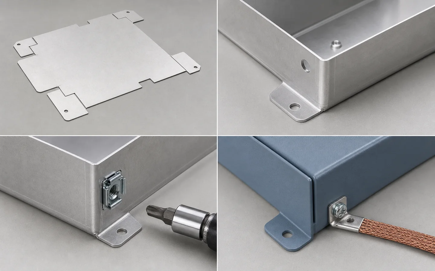
Use this guide
A useful sheet metal model defines the intended finished geometry and functional interfaces. It should not force an unverified bend allowance, relief or sequence merely because CAD can unfold the part. Supplier tooling, material behavior and process affect the manufacturing flat, while the buyer's drawing should identify which formed dimensions, holes, interfaces and appearance zones control acceptance.
Review the complete route: cutting, deburring, forming, hardware, welding, grinding, coating, marking and assembly can interact. A hole that is correct before bending may move afterward; a welded seam may distort a panel; a coating can close a fit. MakeNexa uses the RFQ to resolve these interactions and confirm project-specific capabilities instead of applying universal design limits.
Design priorities
Each area should communicate function while allowing the selected supplier to plan its process.
Specify alloy or grade, temper, thickness, grain or cosmetic direction and acceptable substitutions.
Inside radii, short flanges, returns, hems and closed geometry need tool-access and sequence review.
Holes, slots, louvers, countersinks and hardware near bends may distort or require changed sequencing.
Panels, hinges, latches, connectors, gaskets and internal components should be checked in the top-level model.
Common review gaps
Remove conflicts between model, flat pattern, part drawing and assembly intent.
Treat the supplier's manufacturing flat as process output unless a blank itself is the purchased item.
Prioritize interfaces, datums, angles and overall conditions that affect function or assembly.
Coating, masking, grain, cosmetic faces and grounding can change dimensions, hardware sequence and handling.
Part files alone may not reveal tolerance stacks, tool access, panel gaps, service paths and welding constraints.
Practical choices
Use these as review prompts rather than rigid limits across every supplier and material.
Common thicknesses, realistic radii and accessible bends can reduce special setup when function permits.
Mark interfaces, viewing zones and allowed tooling evidence so effort is applied where it creates value.
Choose hardware, welds, tabs, slots and fasteners with installation, distortion, finish and service in view.
Design decision table
Typical published design practice for press-brake fabrication. Achievable geometry depends on material, thickness and available tooling, and the project requirement is confirmed on the reviewed quote rather than from this table.
| Design area | Typical published value | Supplier review |
|---|---|---|
| Minimum inside bend radius | About 1 times material thickness in 5052-H32 and mild steel; 2 to 3 times in 6061-T6 | The alloy decides feasibility before the tooling does |
| Hole to bend distance | At least 2.5 times material thickness plus the bend radius | Closer and the hole pulls oval during forming |
| Minimum flange length | About 4 times material thickness plus the bend radius, so the flange clears the die | Shorter flanges need special tooling |
| Bend relief | At least material thickness wide where a bend meets an unbent edge | Designed in, or the corner tears |
| Bend angle tolerance | Commonly ±1°, tightening to ±0.5° with added setup and inspection | On a 300 mm panel, 1° is about 5 mm at the free edge |
| Dimension across a bend | Commonly ±0.25 mm on a single bend, accumulating with each additional bend | Which datum face dimensions are measured from |
| Cut-profile tolerance | About ±0.13 mm on a laser-cut flat feature, before any bend error | Flat features hold far tighter than anything across a bend |
| Minimum hole diameter | At least equal to material thickness on laser cutting | A 1 mm hole in 3 mm plate is not a cutting operation |
| Grain direction | A bend running with the grain needs a larger radius than the same bend across it | Grain direction stated on tight bends |
| K-factor | Commonly 0.33 to 0.44, and it sets the flat-pattern length | Why a pattern developed elsewhere comes out the wrong length |
| Common gauges | 1.0 mm, 1.5 mm and 2.0 mm cover most enclosure and bracket work | Gauge checked against hardware minimums, around 0.8 mm for an M3 clinch nut |
| Finishing allowance | Powder at 50 to 100 µm per surface, anodize at 5 to 25 µm | Which holes and threads are masked or reamed after finishing |
Turn the guide into an RFQ
Submit one controlled package that explains the formed part and its assembly job.
Complete packages move faster: revision-matched CAD, critical dimensions, quantity and material notes are enough to open engineering review across the network.
Get a QuoteTop-level assembly plus formed part models and matched drawings
Material, thickness, temper, grain and permitted alternatives
Critical bends, interfaces, datums, gaps and assembly clearances
Hardware, weld, join, access and distortion requirements
Deburr, finish, masking, markings and cosmetic zones
Quantity, inspection, packaging, labeling and delivery context
Questions before routing
These answers prepare the request; the reviewed quote controls project-specific commitments.
No — supply the formed 3D model as the controlling geometry and mark any flat pattern as a reference. Pattern length depends on the K-factor, commonly 0.33 to 0.44, and on the tooling the supplier actually has, so a pattern developed with different assumptions comes out the wrong length. Provide material and thickness, bend radii, grain direction where a bend is tight, and which faces are datums.
At least 2.5 times material thickness plus the bend radius — so in 2 mm material with a 2 mm radius, about 7 mm from the bend line. Closer than that and the hole deforms into an oval as the material stretches around the bend. It is the most common avoidable rework on formed parts. Where a hole must sit closer, the alternatives are piercing after forming, or a relief slot.
It has to be resolved on the drawing. Powder adds 50 to 100 µm per surface, which closes clearance holes and threads; anodize adds 5 to 25 µm growing about half outward. On a hinge fit or a self-clinching thread that is decisive. State whether each critical dimension applies before or after finishing, and mark every feature that is masked or reamed afterward.
It helps considerably, because most sheet-metal problems are tolerance-chain problems. Bend angle at ±1° and across-bend dimensions at ±0.25 mm each accumulate, so a large enclosure can drift several millimetres across a chain of features — and the fix is usually a designed clearance of 0.5 to 1.5 mm or a slotted hole rather than a tighter tolerance. Sharing the assembly lets those decisions be made where they belong.
Because 6061-T6 needs an inside bend radius of about 2 to 3 times material thickness and cracks below that, where 5052-H32 bends at roughly 1 times thickness. 6061 is a machining alloy that is also sold as sheet; 5052 is a forming alloy. For a folded part, 5052 is usually correct — it also resists salt water better and welds without losing a heat-treated condition it never had, at 193 MPa / 28 ksi yield against 6061-T6's 276 MPa.
Next step
Apply the guide to a real drawing and RFQ package. MakeNexa routes capable suppliers from a global network covering competitor-class process categories, then returns a prepared quote or focused clarification for your revision.