 MAKENEXA
Form-and-fit learning
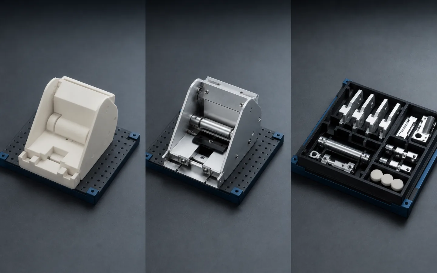
Printed, machined or simply fabricated models can check envelope, ergonomics, access and basic assembly. Label nonfunctional surfaces and substitute materials so stakeholders do not treat the model as performance evidence.
Industry sourcing decision
Early hardware teams often need several routes at once: machined mechanisms, printed fit models, fabricated enclosures, molded parts, hardware and assembly support. The main sourcing problem is not finding a single process; it is keeping revisions, learning objectives, quantities and acceptance criteria aligned while the product changes. MakeNexa reviews the current package and routes it through a global supplier network. Process, material, tolerance, quantity, price, lead time, inspection and supplier fit are confirmed for each RFQ.
Application context
Start by naming the decision the build must support. A fit model may answer envelope and access questions; an engineering prototype may need working interfaces and representative material; a pilot build may test repeat assembly, packaging and release records. Those are different deliverables even if they use the same CAD. Mark the authoritative revision, identify must-work features and list which appearance, strength, life or process behaviors are intentionally outside the build.
Then structure the RFQ so quotes remain comparable while the design evolves. Separate each part and assembly boundary, supply quantities by revision, list approved materials and finishes, and identify purchased hardware, cosmetic references, test responsibility and permitted alternatives. MakeNexa can review route changes and consolidate clarification, but it cannot replace product validation, forecast certainty or the startup's design authority. A fast-looking sample is not evidence that the same route fits repeat production.
Typical program needs
This path connects prototype choices to the files, controls and supplier decisions needed for the next build.
Printed, machined or simply fabricated models can check envelope, ergonomics, access and basic assembly. Label nonfunctional surfaces and substitute materials so stakeholders do not treat the model as performance evidence.
Hinges, latches, mounts, shafts, heat paths, cable routes and sealing interfaces need representative geometry and assembly context. Provide mating parts, hardware and the tests the engineering team will perform after receipt.
Low-volume machining, sheet fabrication, casting-like routes or prototype tooling can support early demand while the design matures. Compare tooling, unit route, revision exposure, inspection and repeatability rather than using quantity alone.
A controlled bill of materials, model and drawing set, approved samples, assembly notes and acceptance checklist reduce dependence on verbal history. The package should explain both what is frozen and what the supplier may question.
Application risks
Startup sourcing slows down when unstated assumptions spread across revisions, suppliers and prototype processes.
A sample can look correct while relying on a different material, wall strategy, tool access or hand adjustment. Keep the design definition in controlled files and record which prototype observations are transferable to the intended route.
Separate suppliers can be useful, but unclear ownership of hardware, finishing, fit-up, assembly and test creates gaps. Define who supplies and accepts each operation, and decide where consolidation adds real control.
File links, chat attachments and unnumbered exports can produce mixed builds. Use one release package with revision, quantity, material, finish and assembly mapping for every line item, then issue changes deliberately.
Terms such as premium or clean do not define grain, color, texture, gate witness, tool mark, edge condition or acceptable variation. Supply controlled zones, reference samples or measurable workmanship criteria.
Sourcing paths
The route can change across builds, provided the team preserves the learning and interfaces that matter.
Group a small set of fit, appearance or mechanism samples around explicit questions. Use flexible processes, narrow the inspection scope to the decision and preserve enough revision data to reproduce the useful result.
Use representative materials and working interfaces when the build must support functional testing. Define critical features, assembly sequence, supplied components and test inputs, then separate engineering results from supplier acceptance.
When repeatability and handoff matter, add stable drawings, a bill of materials, first-article scope, assembly criteria, packaging and change control. Review which prototype processes remain suitable and which need a production-intent route.
Program decision table
Typical published values for the routes common at each hardware development stage. Achievable results depend on the specific part and supplier, and the project requirement is confirmed on the reviewed quote rather than from this table.
| Build objective | Typical published value | Routing consequence |
|---|---|---|
| Form and fit check, 1 to 5 parts | FDM or SLA at ±0.2 mm or ±0.1 mm respectively, in days | Cheapest way to learn whether the geometry is right |
| Functional test, 1 to 20 parts | CNC machining at ±0.125 mm standard practice in production material, or SLS and MJF at ±0.3 mm in PA12 at about 48 MPa | Whether the test depends on material properties |
| Engineering build, 20 to 100 parts | Machining, or urethane casting at ±0.2 mm with silicone moulds lasting 20 to 25 parts | Where per-part cost starts to dominate setup |
| Pilot, 100 to 10,000 parts | Aluminium injection tooling at 1,000 to 10,000 shots, commonly 2 to 4 weeks to first samples | The point at which tooling repays |
| Production, above 10,000 | P20 tooling at about 30 HRC for several hundred thousand shots, commonly 8 to 16 weeks | A different lead time and a different commitment |
| Cost structure at low quantity | At 1 to 10 parts, setup dominates almost entirely; the second part often costs a fraction of the first | Ordering spares is usually cheap |
| Cost structure at high quantity | Cycle time dominates, and cooling scales with the square of the thickest wall | Wall thickness becomes the main design lever |
| Design rules that persist | Uniform wall of 1.0 mm to 3.0 mm, draft of 1° to 2°, ribs at 50 to 60% of the adjoining wall | A part designed for moulding from the start avoids a redesign at pilot |
| Design rules for machining | Pocket depth under about 4 times cutter diameter, internal radii above 1 mm, walls above 0.8 mm | Cost drivers visible in the model long before quoting |
| Revision control | Each revision is a new setup and often new stock; an informally replaced file is how the wrong version gets built | A controlled revision identifier from the first prototype |
| What transfers between stages | Geometry and fit transfer; achievable tolerance, surface and cost at the next quantity often do not | Which conclusions each stage supports |
| What to send suppliers | A 3D model as controlling geometry plus a drawing carrying critical dimensions, material, finish and acceptance | A model alone is not a specification |
Industry RFQ inputs
Package the current design stage clearly enough that suppliers quote the same build and the team can learn from it.
Complete packages move faster: revision-matched CAD, critical dimensions, quantity and material notes are enough to open engineering review across the network.
Get a QuoteState the build objective, product stage and decisions the parts must support
Submit revision-controlled models, drawings, BOM and assembly or mating context
List quantities by part and variant, repeat scenarios and any target build sequence
Define materials, finishes, cosmetic zones, hardware and permitted substitutions
Mark functional interfaces, critical features, inspection needs and team-owned tests
Clarify tooling, supplied components, assembly, packaging and intellectual-property boundaries
Identify what is frozen, what remains open and how revision changes will be issued
Questions before routing
These answers prepare the request; the reviewed quote controls project-specific commitments.
Match the process to how settled the geometry is. While it is still moving, printing at ±0.2 mm answers fit questions in days for very little money and design changes cost nothing. Once geometry stabilises and the questions turn functional, machining in the production material at ±0.125 mm answers them properly. Committing to tooling at 2 to 4 weeks lead before the design settles is the expensive mistake. Process review is part of the RFQ — and the cheapest thing to check early is whether the design is mouldable at all: uniform wall of 1.0 mm to 3.0 mm, 1° to 2° draft, ribs at 50 to 60% of wall.
Ask for both, but understand they are different answers rather than one scaled. At 1 to 10 parts setup dominates the price entirely; at 10,000 the economics are tooling and cycle time, and the route, supplier and even the material may differ. What is genuinely useful early is knowing whether the current design is mouldable — uniform wall of 1.0 mm to 3.0 mm, 1° to 2° draft, ribs at 50 to 60% of wall — because that is cheap to fix now and expensive later.
Yes, and it is normal: print for form, machine for function, cast or bridge-tool for a pilot batch, then mould for production. The discipline that matters is knowing what each stage proves. A printed part carries interlayer strength at only 30 to 70% of its in-plane value; a machined part is isotropic but has no knit lines or fibre orientation; only a moulded part behaves like a moulded part. State what each build must demonstrate.
A 3D model as the controlling geometry with a controlled revision identifier, plus a drawing that carries the critical dimensions and their tolerances, material and grade, finish, edge condition and acceptance basis. The model says what shape the part is; the drawing says what is acceptable. Without the drawing, three suppliers make three different reasonable interpretations, and the differences only surface at assembly.
Usually somewhere around 100 to 1,000 parts, depending on part size and the machined or cast alternative. Below that, machining or urethane casting — where a silicone mould lasts 20 to 25 parts — is cheaper end to end. Aluminium tooling at 1,000 to 10,000 shots and 2 to 4 weeks lead is the normal first step, and it can bridge production while a P20 tool at 8 to 16 weeks is cut. State the quantity ramp so the crossover can be evaluated.
Next step
Send the application context with the controlled part package. MakeNexa routes capable suppliers from a global network covering competitor-class process categories, then returns a prepared quote or focused clarification for your revision.