 MAKENEXA
Exact hardware identity
Provide manufacturer, part number, size, material, finish and approved alternates. If the buyer supplies hardware, define incoming packaging, lot information, overage and how shortages or damaged items are handled.
Manufacturing service decision
Installed hardware turns a manufactured component into a more complete assembly input, but the installation depends on the exact fastener, parent material, receiving feature, access, finish sequence and acceptance method. MakeNexa reviews hardware and base-part sourcing as one network route; brand authorization and universal installation performance are never inferred.
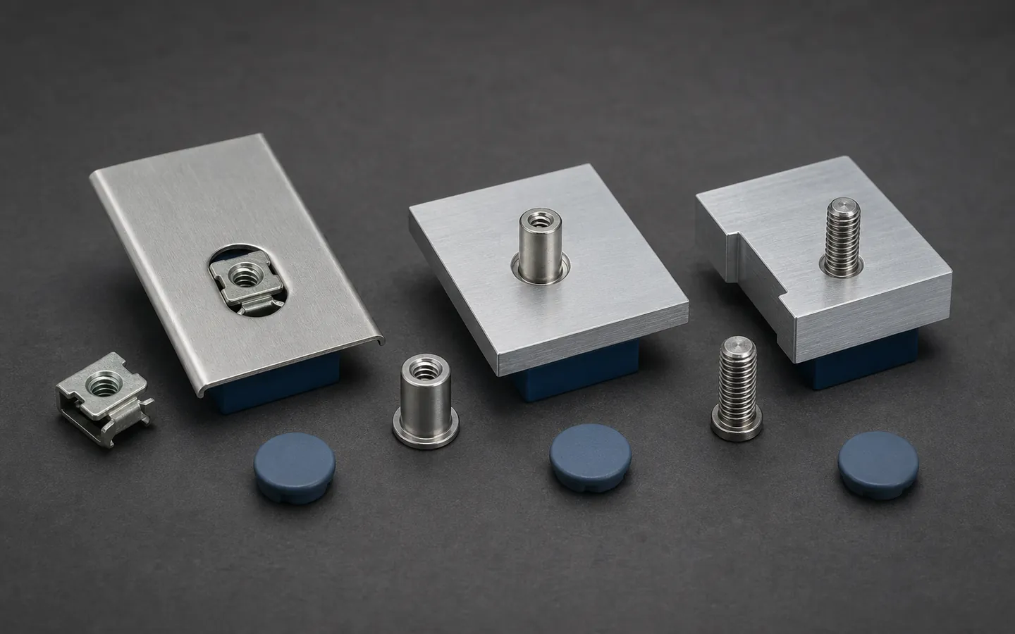
Route decision
A generic note such as install insert or add captive nut leaves critical questions unanswered. Use the manufacturer and exact hardware part number, revision where applicable, material and finish, then connect it to the controlled hole, panel or boss geometry. Identify installation direction, tool access, nearby unsupported walls and the mating assembly. The same hardware can behave differently in a new parent material, thickness, hardness or post-finish condition.
Decide when installation occurs relative to coating, heat treatment, cleaning and marking. Some hardware is installed after finish to protect the coating or preserve fit; other designs require masking, electrical continuity or a pre-finish operation. State whether the requirement is seating, orientation, torque, push-out, pull-out or another project-specific check. Testing and sampling should match the real risk rather than an assumed universal standard.
Best-fit parts and programs
Hardware installation fits when the base part and supplied fastener can be controlled through one defined final condition.
Provide manufacturer, part number, size, material, finish and approved alternates. If the buyer supplies hardware, define incoming packaging, lot information, overage and how shortages or damaged items are handled.
Control hole size, thickness, countersink, edge distance, hardness and local support as required by the selected hardware. Identify whether dimensions apply before or after plating, paint or another finish.
Show the insertion side, tool clearance, protected surfaces, directional features and nearby geometry. Confirm that installation forces can be supported without distorting the part or damaging the finish.
Define seating, height, flushness, rotation, orientation, thread condition or project-specific retention checks. Use the mating fastener and assembly context when functional verification is required.
Feasibility checks
Most issues cannot be solved by selecting a familiar brand name alone.
Supplier guidance may assume a parent material, thickness, hardness and prepared hole. Review those conditions against the actual released part instead of treating a catalog range as automatic acceptance.
Coating can reduce a hole, cover serrations or affect seating surfaces. Define mask, allowance, installation sequence and final-state inspection before the part and finish routes are quoted.
A thread may gauge correctly but still fail the actual assembly because of engagement, length, shoulder or access. Provide mating fastener information and torque or use context where it changes acceptance.
Studs, standoffs and cosmetic hardware may need protective separators, caps or orientation-controlled packaging. Describe final handling so a correct installation arrives in acceptable condition.
Route options
The route should place hardware where receiving geometry, finish and acceptance can be controlled most effectively.
Combine part manufacture, finish and hardware when one route can manage feature allowances, sequence and final inspection. Include the hardware in the BOM and finished-component drawing.
Use a controlled handoff when the finish source or specification is fixed. Define receiving condition, protected zones, shipping evidence and how finish damage during installation is dispositioned.
Ship loose components when the buyer controls installation. Define counts, exact identity, lot separation and packaging; do not use this route if the receiving team expects an installed and inspected component.
Decision comparison
Typical published practice for installed captive hardware. Exact minimum thicknesses, edge distances and installation forces come from the specific hardware manufacturer's data, and the project requirement is confirmed on the reviewed quote rather than from this table.
| Interface | Typical published requirement | Acceptance question |
|---|---|---|
| Minimum sheet thickness | Each self-clinching part publishes a minimum host thickness — commonly around 0.8 mm for an M3 clinch nut and more for larger sizes | Whether the chosen gauge supports the hardware at all |
| Minimum edge distance | Published per part and typically a small multiple of the shank diameter; too close and the sheet bulges or tears | Hardware positions checked against the edge, not just against the pattern |
| Host hardness limit | Self-clinching hardware requires the sheet to be softer than the hardware — commonly stated as a maximum host hardness | Whether the material and temper suit the hardware |
| Installation method | A parallel-acting press with controlled force, not a hammer or a standard punch press | A supplier-capability question |
| Hole size | The mounting hole is specified by the hardware manufacturer to a tight tolerance, commonly within about ±0.05 mm | The published hole size on the drawing, not a clearance hole |
| Effect on the far side | Clinching displaces host material; the reverse face shows a witness ring and must be flat to seat | Whether the far side is a cosmetic or sealing surface |
| Sequence with finishing | Normally installed before coating and then masked, since installation afterward damages the film | Which hardware is masked and which is installed later |
| Coating on threads | Powder adds 50 to 100 µm per surface and anodize 5 to 25 µm — both close a small thread | Which threads are masked or chased after finishing |
| Galvanic pairing | Stainless hardware in an aluminium panel, or steel hardware against magnesium, forms a galvanic couple | The pair reviewed against the service environment |
| Equivalent parts | Different manufacturers' equivalents differ in knurl form, installation force and published performance | Whether an equivalent is permitted, stated on the drawing |
| Inspection | Push-out and torque-out to stated values with a test method and sample plan | The acceptance test named rather than inferred from appearance |
| Blind and thin applications | Where the panel is too thin or access is single-sided, rivet nuts and other blind hardware replace clinch parts with different performance | Whether the design has two-sided access at all |
| Thicker-gauge hardware | Larger self-clinching parts commonly require 1.5 mm and 2.0 mm host material; the minimum rises with thread size | The hardware chosen against the gauge, not after it |
| Standoffs and spacers | Clinch standoffs commonly need 3.0 mm and more of clearance behind the panel for the shank | Whether the assembly stack allows for it |
| Anodize allowance | Type II anodize adds 5 µm to 25 µm, enough to close a fine thread on installed hardware | Which threads are masked |
| Plating allowance | Zinc plating adds 5 µm to 25 µm and electroless nickel up to 50 µm on every surface | Whether hardware is installed before or after plating |
| Hole tolerance | The published mounting hole is commonly held within about ±0.05 mm; a clearance hole does not clinch | The hardware manufacturer's hole size on the drawing |
Quote inputs
Provide the exact hardware and final component requirement rather than a shorthand installation note.
Complete packages move faster: revision-matched CAD, critical dimensions, quantity and material notes are enough to open engineering review across the network.
Get a QuoteList manufacturer, part number, size, material, finish, quantity and approved alternates
Provide the controlled parent-part model and drawing with receiving feature dimensions
State parent material, thickness, hardness and dimensional condition before and after finish
Show insertion direction, support, tool access, orientation and surfaces protected from damage
Define the sequence relative to heat treatment, coating, marking, cleaning and other assembly
Set seating, thread, torque, retention, sampling, documentation and protective packaging needs
Questions before routing
These answers prepare the request; the reviewed quote controls project-specific commitments.
Self-clinching nuts, studs and standoffs, blind rivet nuts, threaded inserts and press-fit hardware all route through the supplier network. What decides feasibility is the host rather than availability: every part publishes a minimum sheet thickness — commonly around 0.8 mm for an M3 clinch nut, rising with thread size to 1.5 mm and 2.0 mm — a minimum edge distance, and a maximum host hardness, since clinching works by displacing material into an undercut. Check those against your gauge and material before fixing the hole pattern, and supplier fit is confirmed on the reviewed quote.
Yes where the drawing permits it, and it is worth stating explicitly either way. Equivalents from different manufacturers differ in knurl form, required hole size — commonly held within about ±0.05 mm — installation force and published pull-out and torque values, so an equivalent is not automatically a substitute. The workable form is to give the part number, say whether equivalents are acceptable, and name the published performance figures that must be met. That turns a brand question into a requirement question, which is what a supplier can actually hold and verify.
Normally before, then masked. Installing after coating damages the film around the hardware, and the clinching operation would mark the finished surface. But coating over an installed thread closes it — powder adds 50 to 100 µm per surface and anodize 5 to 25 µm — so the thread has to be masked or chased afterward. State the sequence and the masking on the drawing rather than leaving it to the finishing supplier.
By push-out and torque-out testing to stated values with a defined method and sample plan, not by appearance. Correct installation is not visible: a clinch nut that looks seated can have been pressed into a sheet that is too hard or too close to an edge, and it fails at a fraction of its published value. State the required push-out force, torque, sample scope and test method.
Usually edge distance or host hardness. Clinching works by displacing host material into an undercut, so if the hardware sits closer to an edge or a hole than its published minimum, the displaced material has nowhere to go and the sheet bulges or tears. The other common cause is a host that is too hard — a work-hardened or heat-treated panel does not flow into the undercut. Check both against the manufacturer's data before fixing the hole pattern.
Next step
Send geometry and process requirements for review. MakeNexa routes capable suppliers from a global network covering competitor-class process categories, then returns a prepared quote or focused clarification for your revision.