 MAKENEXA
Flat and parallel faces
Ground faces can support mounting, spacing, sealing or reference needs when flatness, parallelism, thickness and datum relationship are defined in the final material condition.
Manufacturing service decision
Precision grinding is most useful when the final dimension, relationship or surface cannot be managed by an earlier operation alone. Material condition, heat treatment, stock allowance, part support, datum strategy, surface integrity and measurement method must agree. MakeNexa reviews the requirement across its supplier network; exact process, achievable tolerance, roughness, price, timing and evidence remain specific to the part and RFQ.
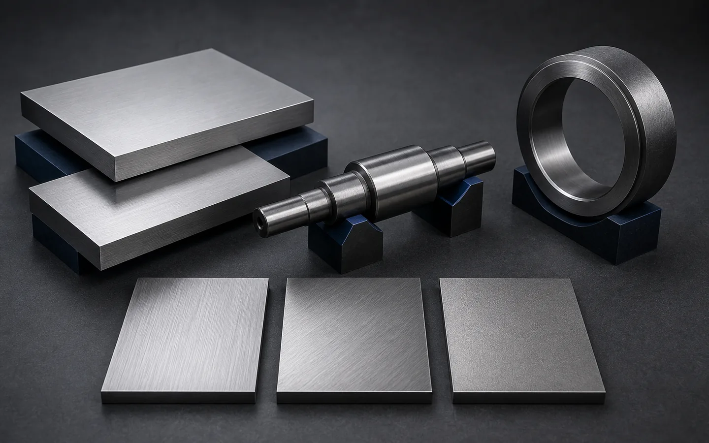
Route decision
Identify the surfaces or diameters that govern fit, seal, motion, alignment or wear, and state their relationship to functional datums. Define material grade and condition, prior and later operations, heat treatment, coating, hardness evidence where required, stock allowance and whether sharp transitions, shoulders or thin sections create support risk. Grinding every surface by default can add handling and cost without improving function.
The reviewed supplier route may involve surface, cylindrical, internal, centerless, jig or another grinding method depending on geometry and access. Dressing, workholding, thermal control, spark-out, cleaning and measurement are process decisions, not website promises. State the final accepted dimension and surface condition plus the measurement environment and method where they materially affect agreement.
Best-fit parts and programs
The route should connect each ground feature to function, process state and a reproducible inspection method.
Ground faces can support mounting, spacing, sealing or reference needs when flatness, parallelism, thickness and datum relationship are defined in the final material condition.
Cylindrical or internal grinding may support bearing, seal or alignment features where size, roundness, cylindricity, taper and surface are functionally related. Provide mating and edge-transition context.
Grinding may establish final geometry after heat treatment when allowance, distortion, hardness, decarburization or case-depth concerns are controlled. The material and heat-treatment records must match the released requirement.
Roughness, lay and surface integrity can matter for sealing, sliding, contact or later coating. Specify the needed parameter and evaluation rather than requesting a generally smooth appearance.
Feasibility checks
Tolerance, surface and measurement must refer to the same feature, condition and datum system.
Earlier machining and heat treatment need enough controlled allowance for cleanup without leaving excessive removal, stress or cycle. Coordinate nominal condition and transition stock with the proposed route.
Magnetic, mechanical or other workholding can influence flexible geometry. Define free-state acceptance, permitted support and unclamped verification for features that relax after grinding.
A low roughness value alone does not define lay, waviness, defects, sampling or mating performance. Tie surface requirements to the interface and specify the parameter and evaluation standard.
Wheel access, corner radius, undercuts, reliefs and burr-sensitive exits affect full cleanup and adjacent features. Model or call out transition geometry and protected edges.
Route options
Compare grinding with machining, honing, lapping or other finishing only against the actual functional requirement.
Use for accessible planar faces where thickness, flatness, parallelism and surface are controlled with suitable support and final-state inspection.
Use for external diameters, bores and related shoulders when centers, datums, access, transition geometry and round-form requirements support the process.
Precision machining, honing, lapping, polishing or another method may better match geometry or surface function. Review the complete feature and evidence instead of prescribing a method from tolerance alone.
Decision comparison
Typical published capability for surface and cylindrical grinding. Achievable tolerance and finish depend on machine, wheel, material condition and part geometry, and the project requirement is confirmed on the reviewed quote rather than from this table.
| Decision layer | Typical published value | Routing consequence |
|---|---|---|
| Achievable size tolerance | ±0.005 mm (±0.0002 in) is routine, against ±0.025 mm (±0.001 in) as precision machining practice | The reason to add a second process after CNC |
| Surface finish | Ra 0.2 to 0.4 µm from a normal finish grind; Ra 0.1 µm and better with fine wheels and slow passes | Against Ra 0.8 µm as the best a milling finishing pass gives |
| Flatness | Commonly held within 0.005 mm over a 100 mm span on a rigid part | Whether the part is rigid enough to hold it once unclamped |
| Cylindrical roundness | Within about 0.002 mm on centred work | Bearing journals, seal lands and locating diameters |
| Grinding stock allowance | 0.2 to 0.4 mm per surface left after machining and heat treatment | Too little and heat-treatment distortion cannot be cleaned up; too much and cycle time rises |
| Hardness threshold | Above roughly 45 HRC conventional cutting stops being practical and grinding becomes the only route | The hardness callout decides the process, not a preference |
| Sequence with heat treatment | Rough machine, heat treat, then grind — quench and temper move the part well past ±0.05 mm | Which dimensions are final in which condition |
| Workholding distortion | Magnetic chucks and clamping deflect thin parts; the flatness measured while held is not the flatness in the free state | How flatness is to be measured, stated on the drawing |
| Thermal effect | Grinding puts heat into the surface; heavy passes can burn and re-temper a hardened layer | Whether a surface-integrity requirement applies |
| Surface texture standard | ASME B46.1 is the usual reference where the measurement method matters | That an Ra number alone leaves the method open |
| Wheel access | Internal bores, corners and blind features limit which grinding route applies | Whether the geometry is grindable at all |
| Cost basis | Grinding is priced by surface area and stock removal, not by part complexity | Whether every surface needs it, or only the functional ones |
Quote inputs
Identify the final characteristics and process state so the grinding route can be reviewed without guessing.
Complete packages move faster: revision-matched CAD, critical dimensions, quantity and material notes are enough to open engineering review across the network.
Get a QuoteSubmit the controlled model, drawing, revision and functional interface context
State material grade, condition, heat treatment, hardness and required records
Mark ground features, functional datums, transitions, reliefs and protected edges
Define size, form, orientation, roughness, lay and before-or-after-coating state
Provide prior-operation condition, available stock and later cleaning or finish scope
List quantities, measurement environment, support state, sampling and report needs
Questions before routing
These answers prepare the request; the reviewed quote controls project-specific commitments.
Two triggers, and both are visible on the drawing. Tolerance: below about ±0.025 mm (±0.001 in), milling and turning start needing temperature control and added inspection, while grinding holds ±0.005 mm (±0.0002 in) routinely. Finish: Ra 0.8 µm is roughly the practical floor for a milling finishing pass, while grinding delivers Ra 0.2 to 0.4 µm. Hardness is the third: above roughly 45 HRC, grinding is the only practical route.
±0.005 mm (±0.0002 in) on size is routine, with flatness commonly within 0.005 mm over a 100 mm span and cylindrical roundness within about 0.002 mm on centred work — all routable through the network, including on hardened material above 45 HRC where conventional cutting stops being practical. Three things move the result for a specific part: rigidity, since a thin part deflects under workholding and springs back on release; wheel access, since internal bores and blind features constrain the route; and how flatness is measured, because a clamped part is not the free-state part. Give the feature, tolerance, datum scheme and measurement condition.
After, essentially always. Quench and temper move a part well past ±0.05 mm, so anything ground beforehand is lost. The normal sequence is rough and semi-finish machine, heat treat, then grind — with 0.2 to 0.4 mm of stock left per surface so the distortion can be cleaned up. Too little allowance and the ground surface does not clean up; too much and the cycle grows. State which dimensions apply in which condition.
Usually not on its own. An Ra number such as Ra 0.4 µm fixes the average height but not the measurement method, the direction of lay, waviness, or the surface integrity underneath — and heavy grinding passes can burn and re-temper a hardened surface without changing Ra at all. ASME B46.1 is the usual reference where the method matters. State the roughness, the direction, the datum and any surface-integrity requirement separately.
Because it was measured while held. Magnetic chucks and mechanical clamping deflect thin and asymmetric parts, and a surface ground flat under that load springs back when released — a part reading within 0.005 mm on the machine can read several times that in the free state. State the free-state condition, the support method and the measurement points on the drawing, or the flatness requirement will not repeat between supplier and receiving inspection.
Next step
Send geometry and process requirements for review. MakeNexa routes capable suppliers from a global network covering competitor-class process categories, then returns a prepared quote or focused clarification for your revision.